Chrysler PT Cruiser. Manual - part 877


  Index      Chrysler     Chrysler PT Cruiser - service repair manual 2005 year


Search            


Content   ..  875  876  877  878   ..


Chrysler PT Cruiser. Manual - part 877


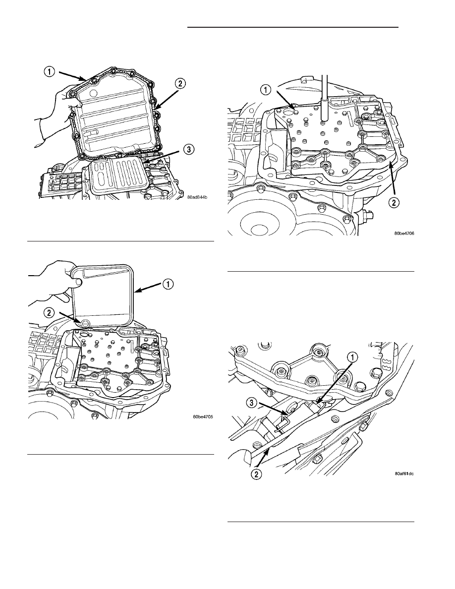
(10) Remove oil pan (Fig. 364).

(11) Remove oil filter (Fig. 365).

(12) Remove the valve body-to-transaxle case bolts

(Fig. 366).

NOTE: To ease removal of the valve body, turn the
manual valve lever fully clockwise to low or first
gear.

(13) Remove park rod rollers from guide bracket

and remove valve body from transaxle (Fig. 367) (Fig.
368).

Fig. 364 Oil Pan

1 - OIL PAN
2 - 1/8 INCH BEAD OF RTV SEALANT
3 - OIL FILTER

Fig. 365 Oil Filter and O-Ring

1 - OIL FILTER
2 - O-RING

Fig. 366 Valve Body-to-Case Bolts

1 - VALVE BODY ATTACHING BOLTS (18)
2 - VALVE BODY

Fig. 367 Push Park Rod Rollers from Guide Bracket

1 - PARK SPRAG ROLLERS
2 - SCREWDRIVER
3 - PARK SPRAG GUIDE BRACKET

21 - 462

41TE AUTOMATIC TRANSAXLE

PT

TRANSMISSION RANGE SENSOR (Continued)

CAUTION: The valve body manual shaft pilot may
distort and bind the manual valve if the valve body
is mishandled or dropped.

(14) Remove manual shaft seal (Fig. 369).

(15) Remove TRS retaining screw (Fig. 370).

(16) Slide Transmission Range Sensor up the man-

ual shaft and remove (Fig. 371).

Fig. 368 Valve Body Removal/Installation

1 - VALVE BODY

Fig. 369 Remove Manual Shaft Seal

1 - SEAL
2 - MANUAL SHAFT

Fig. 370 Remove Retaining Screw

1 - TRANSMISSION RANGE SENSOR
2 - MANUAL VALVE CONTROL PIN
3 - RETAINING SCREW

Fig. 371 Remove Transmission Range Sensor

1 - TRANSMISSION RANGE SENSOR
2 - VALVE BODY

PT

41TE AUTOMATIC TRANSAXLE

21 - 463

TRANSMISSION RANGE SENSOR (Continued)

INSTALLATION

The valve body assembly must be removed to gain

access to and replace the transmission range sensor.

(1) Install transmission range sensor (Fig. 371).
(2) Tighten retaining screw (Fig. 370) to 5 N·m (45

in. lbs.).

(3) Install manual shaft seal (Fig. 369).
(4) Guide park rod rollers into guide bracket while

installing valve body to the transaxle case (Fig. 367)
(Fig. 368).

(5) Install the valve body-to-case bolts (Fig. 366)

and torque to 12 N·m (105 in. lbs.).

(6) Install the oil filter (Fig. 365). Inspect the

o-ring for damage and replace as necessary.

(7) Install an 1/8’ bead of RTV as shown in (Fig.

364) and install pan to case.

(8) Install oil pan bolts (Fig. 363) and torque to 19

N·m (165 in. lbs.) torque.

(9) Lower vehicle.
(10) Connect transmission range sensor connector.
(11) Install manual valve lever to manual valve.
(12) Install gear shift cable to manual valve lever

(Fig. 362).

(13) Install the battery tray (Fig. 361).
(14) Install the battery and hold down clamp (Fig.

360).

(15) Install air cleaner assembly (Fig. 359).
(16) Connect battery cables.
(17) Fill transaxle with ATF+4 (Automatic Trans-

mission Fluid–Type 9602). Refer to Fluid Level and
Condition in this Group.

VALVE BODY

DESCRIPTION

The valve body assembly consists of a cast alumi-

num valve body, a separator plate, and transfer
plate. The valve body contains valves and check balls
that control fluid delivery to the torque converter
clutch, solenoid/pressure switch assembly, and fric-
tional clutches. The valve body contains the following
components (Fig. 372):

• Regulator valve

• Solenoid switch valve

• Manual valve

• Converter clutch switch valve

• Converter clutch control valve

• Torque converter regulator valve

• Low/Reverse switch valve
In addition, the valve body also contains the ther-

mal valve, #2,3&4 check balls, the #5 (overdrive)
check valve and the 2/4 accumulator assembly. (Refer
to 21 - TRANSMISSION/TRANSAXLE/AUTOMATIC
- 41TE/VALVE BODY - DISASSEMBLY)

OPERATION

NOTE: Refer to the Hydraulic Schematics for a
visual aid in determining valve location, operation
and design.

REGULATOR VALVE

The regulator valve controls hydraulic pressure in

the transaxle. It receives unregulated pressure from
the pump, which works against spring tension to
maintain oil at specific pressures. A system of sleeves
and ports allows the regulator valve to work at one of
three predetermined pressure levels. Regulated oil
pressure is also referred to as “line pressure.”

SOLENOID SWITCH VALVE

The solenoid switch valve controls line pressure

from the LR/CC solenoid. In one position, it allows
the low/reverse clutch to be pressurized. In the other,
it directs line pressure to the converter control and
converter clutch valves.

MANUAL VALVE

The manual valve is operated by the mechanical

shift linkage. Its primary responsibility is to send
line pressure to the appropriate hydraulic circuits
and solenoids. The valve has three operating ranges
or positions.

CONVERTER CLUTCH SWITCH VALVE

The main responsibility of the converter clutch

switch valve is to control hydraulic pressure applied
to the front (off) side of the converter clutch piston.
Line pressure from the regulator valve is fed to the
torque converter regulator valve, where it passes
through the valve, and is slightly regulated. The
pressure is then directed to the converter clutch
switch valve and to the front side of the converter
clutch piston. This pressure pushes the piston back
and disengages the converter clutch.

CONVERTER CLUTCH CONTROL VALVE

The converter clutch control valve controls the

back (on) side of the torque converter clutch. When
the PCM/TCM energizes or modulates the LR/CC
solenoid to apply the converter clutch piston, both
the converter clutch control valve and the converter
control valve move, allowing pressure to be applied to
the back side of the clutch.

T/C REGULATOR VALVE

The torque converter regulator valve slightly regu-

lates the flow of fluid to the torque converter.

21 - 464

41TE AUTOMATIC TRANSAXLE

PT

TRANSMISSION RANGE SENSOR (Continued)

LOW/REVERSE SWITCH VALVE

The low/reverse clutch is applied from different

sources, depending on whether low (1st) gear or
reverse is selected. The low/reverse switch valve
alternates positions depending on from which direc-
tion fluid pressure is applied. By design, when the
valve is shifted by fluid pressure from one channel,
the opposing channel is blocked. The switch valve
alienates the possibility of a sticking ball check, thus
providing consistent application of the low/reverse
clutch under all operating conditions.

REMOVAL

(1) Disconnect the battery cables.
(2) Remove air cleaner assembly (Fig. 373).

Fig. 372 Valve Body Assembly

1 - VALVE BODY

5 - MANUAL VALVE

2 - T/C REGULATOR VALVE

6 - CONVERTER CLUTCH SWITCH VALVE

3 - L/R SWITCH VALVE

7 - SOLENOID SWITCH VALVE

4 - CONVERTER CLUTCH CONTROL VALVE

8 - REGULATOR VALVE

Fig. 373 Air Cleaner Assembly Removal/Installation

1 - AIR CLEANER ASSEMBLY

PT

41TE AUTOMATIC TRANSAXLE

21 - 465

VALVE BODY (Continued)


Content   ..  875  876  877  878   ..