Chrysler PT Cruiser. Manual - part 875


  Index      Chrysler     Chrysler PT Cruiser - service repair manual 2005 year


Search            


Content   ..  873  874  875  876   ..


Chrysler PT Cruiser. Manual - part 875


IMPELLER

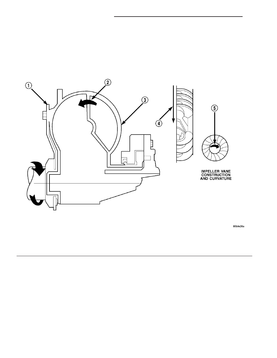
The impeller (Fig. 348) is an integral part of the

converter housing. The impeller consists of curved
blades placed radially along the inside of the housing
on the transmission side of the converter. As the con-
verter housing is rotated by the engine, so is the
impeller, because they are one and the same and are
the driving member of the system.

Fig. 348 Impeller

1 - ENGINE FLEXPLATE

4 - ENGINE ROTATION

2 - OIL FLOW FROM IMPELLER SECTION INTO TURBINE
SECTION

5 - ENGINE ROTATION

3 - IMPELLER VANES AND COVER ARE INTEGRAL

21 - 454

41TE AUTOMATIC TRANSAXLE

PT

TORQUE CONVERTER (Continued)

TURBINE

The turbine (Fig. 349) is the output, or driven,

member of the converter. The turbine is mounted
within the housing opposite the impeller, but is not
attached to the housing. The input shaft is inserted
through the center of the impeller and splined into
the turbine. The design of the turbine is similar to
the impeller, except the blades of the turbine are
curved in the opposite direction.

Fig. 349 Turbine

1 - TURBINE VANE
2 - ENGINE ROTATION
3 - INPUT SHAFT

4 - PORTION OF TORQUE CONVERTER COVER
5 - ENGINE ROTATION
6 - OIL FLOW WITHIN TURBINE SECTION

PT

41TE AUTOMATIC TRANSAXLE

21 - 455

TORQUE CONVERTER (Continued)

STATOR

The stator assembly (Fig. 350) is mounted on a sta-

tionary shaft which is an integral part of the oil
pump. The stator is located between the impeller and
turbine within the torque converter case (Fig. 351).
The stator contains an over-running clutch, which
allows the stator to rotate only in a clockwise direc-
tion. When the stator is locked against the over-run-
ning clutch, the torque multiplication feature of the
torque converter is operational.

TORQUE CONVERTER CLUTCH (TCC)

The TCC (Fig. 352) was installed to improve the

efficiency of the torque converter that is lost to the
slippage of the fluid coupling. Although the fluid cou-
pling provides smooth, shock–free power transfer, it
is natural for all fluid couplings to slip. If the impel-
ler and turbine were mechanically locked together, a
zero slippage condition could be obtained. A hydraulic
piston was added to the turbine, and a friction mate-
rial was added to the inside of the front cover to pro-
vide this mechanical lock-up.

OPERATION

The converter impeller (Fig. 353) (driving member),

which is integral to the converter housing and bolted
to the engine drive plate, rotates at engine speed.
The converter turbine (driven member), which reacts
from fluid pressure generated by the impeller, rotates
and turns the transmission input shaft.

TURBINE

As the fluid that was put into motion by the impel-

ler blades strikes the blades of the turbine, some of
the energy and rotational force is transferred into the

turbine and the input shaft. This causes both of them
(turbine and input shaft) to rotate in a clockwise
direction following the impeller. As the fluid is leav-

Fig. 350 Stator Components

1 - CAM (OUTER RACE)
2 - ROLLER
3 - SPRING
4 - INNER RACE

Fig. 351 Stator Location

1 - STATOR
2 - IMPELLER
3 - FLUID FLOW
4 - TURBINE

Fig. 352 Torque Converter Clutch (TCC)

1 - IMPELLER FRONT COVER
2 - THRUST WASHER ASSEMBLY
3 - IMPELLER
4 - STATOR
5 - TURBINE
6 - PISTON
7 - FRICTION DISC

21 - 456

41TE AUTOMATIC TRANSAXLE

PT

TORQUE CONVERTER (Continued)

ing the trailing edges of the turbine’s blades it con-
tinues in a “hindering” direction back toward the
impeller. If the fluid is not redirected before it strikes
the impeller, it will strike the impeller in such a
direction that it would tend to slow it down.

STATOR

Torque multiplication is achieved by locking the

stator’s over-running clutch to its shaft (Fig. 354).
Under stall conditions (the turbine is stationary), the
oil leaving the turbine blades strikes the face of the
stator blades and tries to rotate them in a counter-
clockwise direction. When this happens the over–run-
ning clutch of the stator locks and holds the stator
from rotating. With the stator locked, the oil strikes
the stator blades and is redirected into a “helping”
direction before it enters the impeller. This circula-
tion of oil from impeller to turbine, turbine to stator,
and stator to impeller, can produce a maximum
torque multiplication of about 2.4:1. As the turbine
begins to match the speed of the impeller, the fluid
that was hitting the stator in such as way as to
cause it to lock–up is no longer doing so. In this con-
dition of operation, the stator begins to free wheel
and the converter acts as a fluid coupling.

Fig. 353 Torque Converter Fluid Operation

1 - APPLY PRESSURE

3 - RELEASE PRESSURE

2 - THE PISTON MOVES SLIGHTLY FORWARD

4 - THE PISTON MOVES SLIGHTLY REARWARD

Fig. 354 Stator Operation

1 - DIRECTION STATOR WILL FREE WHEEL DUE TO OIL
PUSHING ON BACKSIDE OF VANES
2 - FRONT OF ENGINE
3 - INCREASED ANGLE AS OIL STRIKES VANES
4 - DIRECTION STATOR IS LOCKED UP DUE TO OIL PUSHING
AGAINST STATOR VANES

PT

41TE AUTOMATIC TRANSAXLE

21 - 457

TORQUE CONVERTER (Continued)


Content   ..  873  874  875  876   ..