Chrysler PT Cruiser. Manual - part 837


  Index      Chrysler     Chrysler PT Cruiser - service repair manual 2005 year


Search            


Content   ..  835  836  837  838   ..


Chrysler PT Cruiser. Manual - part 837


MANUAL VALVE

The manual valve is operated by the mechanical

shift linkage. Its primary responsibility is to send
line pressure to the appropriate hydraulic circuits
and solenoids. The valve has three operating ranges
or positions.

CONVERTER CLUTCH SWITCH VALVE

The main responsibility of the converter clutch

switch valve is to control hydraulic pressure applied
to the front (off) side of the converter clutch piston.
Line pressure from the regulator valve is fed to the
torque converter regulator valve, where it passes
through the valve, and is slightly regulated. The
pressure is then directed to the converter clutch
switch valve and to the front side of the converter
clutch piston. This pressure pushes the piston back
and disengages the converter clutch.

CONVERTER CLUTCH CONTROL VALVE

The converter clutch control valve controls the

back (on) side of the torque converter clutch. When
the PCM/TCM energizes or modulates the LR/CC
solenoid to apply the converter clutch piston, both
the converter clutch control valve and the converter
control valve move, allowing pressure to be applied to
the back side of the clutch.

T/C REGULATOR VALVE

The torque converter regulator valve slightly regu-

lates the flow of fluid to the torque converter.

LOW/REVERSE SWITCH VALVE

The low/reverse clutch is applied from different

sources, depending on whether low (1st) gear or
reverse is selected. The low/reverse switch valve
alternates positions depending on from which direc-
tion fluid pressure is applied. By design, when the
valve is shifted by fluid pressure from one channel,
the opposing channel is blocked. The switch valve
alienates the possibility of a sticking ball check, thus
providing consistent application of the low/reverse
clutch under all operating conditions.

REMOVAL

(1) Disconnect the battery cables.
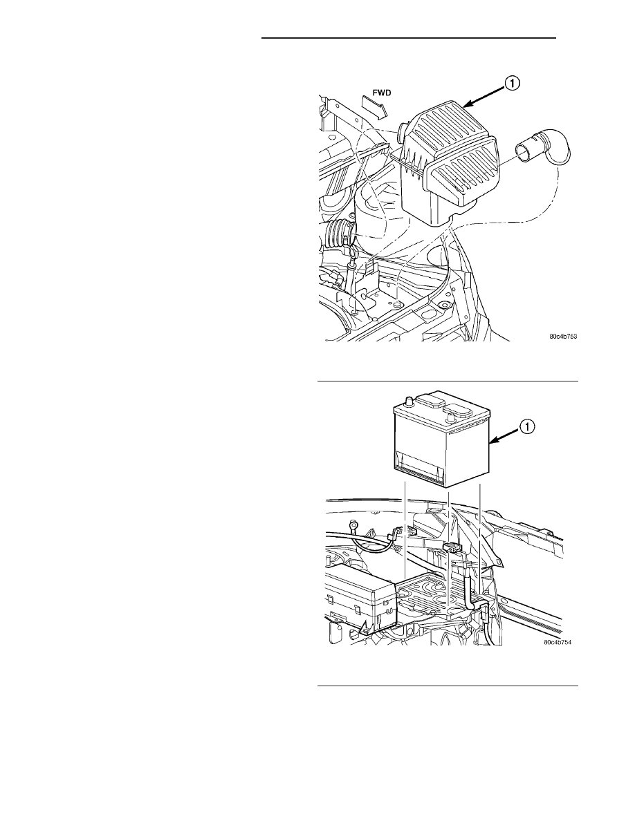
(2) Remove air cleaner assembly (Fig. 373).
(3) Remove the battery hold down clamp and

remove the battery (Fig. 374).

Fig. 373 Air Cleaner Assembly Removal/Installation

1 - AIR CLEANER ASSEMBLY

Fig. 374 Battery Removal/Installation

1 - BATTERY

21 - 302

40TE AUTOMATIC TRANSAXLE

PT

VALVE BODY (Continued)

(4) Remove the battery tray (Fig. 375).

(5) Disconnect gearshift cable from manual valve

lever (Fig. 376).

(6) Remove manual valve lever from manual shaft.
(7) Raise vehicle on hoist.
(8) Remove oil pan bolts (Fig. 377).

(9) Remove oil pan (Fig. 378).

Fig. 375 Battery Tray Removal/Installation

1 - BATTERY TRAY

Fig. 376 Gearshift Cable at Manual Valve Lever

1 - GEARSHIFT CABLE
2 - MANUAL VALVE LEVER

Fig. 377 Oil Pan Bolts

1 - OIL PAN BOLTS (USE RTV UNDER BOLT HEADS)

Fig. 378 Oil Pan

1 - OIL PAN
2 - 1/8 INCH BEAD OF RTV SEALANT
3 - OIL FILTER

PT

40TE AUTOMATIC TRANSAXLE

21 - 303

VALVE BODY (Continued)

(10) Remove oil filter (Fig. 379).

(11) Remove the valve body-to-transaxle case bolts

(Fig. 380).

NOTE: To ease removal of the valve body, turn the
manual valve lever fully clockwise to low or first
gear.

(12) Remove park rod rollers from guide bracket

and remove valve body from transaxle (Fig. 381) (Fig.
382).

CAUTION: The valve body manual shaft pilot may
distort and bind the manual valve if the valve body
is mishandled or dropped.

Fig. 379 Oil Filter

1 - OIL FILTER
2 - O-RING

Fig. 380 Valve Body Attaching Bolts

1 - VALVE BODY ATTACHING BOLTS (18)
2 - VALVE BODY

Fig. 381 Push Park Rod Rollers from Guide Bracket

1 - PARK SPRAG ROLLERS
2 - SCREWDRIVER
3 - PARK SPRAG GUIDE BRACKET

Fig. 382 Valve Body Removal/Installation

1 - VALVE BODY

21 - 304

40TE AUTOMATIC TRANSAXLE

PT

VALVE BODY (Continued)

(13) Remove and tag overdrive and underdrive

accumulators (Fig. 383).

DISASSEMBLY

NOTE: If valve body assembly is being recondi-
tioned, the PCM/TCM Quick Learn Procedure must
be performed. (Refer to 8 - ELECTRICAL/ELEC-
TRONIC

CONTROL

MODULES/TRANSMISSION

CONTROL MODULE - STANDARD PROCEDURE)

(1) Remove manual shaft seal (Fig. 384).

(2) Remove Transmission Range Sensor retaining

screw (Fig. 385).

(3) Remove

Manual

Shaft/Rooster

Comb

and

Transmission Range Sensor (Fig. 386).

Fig. 383 Underdrive and Overdrive Accumulators

1 - OVERDRIVE PISTON AND SPRING
2 - UNDERDRIVE PISTON AND SPRING

Fig. 384 Manual Shaft Seal

1 - SEAL
2 - MANUAL SHAFT

Fig. 385 Remove Transmission Range Sensor

1 - TRANSMISSION RANGE SENSOR
2 - MANUAL VALVE CONTROL PIN
3 - RETAINING SCREW

Fig. 386 Manual Shaft/Rooster Comb and

Transmission Range Sensor

1 - TRANSMISSION RANGE SENSOR
2 - MANUAL SHAFT
3 - ROOSTER COMB

PT

40TE AUTOMATIC TRANSAXLE

21 - 305

VALVE BODY (Continued)


Content   ..  835  836  837  838   ..