Chrysler PT Cruiser. Manual - part 695


  Index      Chrysler     Chrysler PT Cruiser - service repair manual 2005 year


Search            


Content   ..  693  694  695  696   ..


Chrysler PT Cruiser. Manual - part 695


DIAGNOSIS AND TESTING

CHECKING ENGINE OIL PRESSURE

Check oil pressure using a gauge at oil pressure

switch location.

(1) Remove pressure sending unit. The pressure

sending unit is located on the oil filter cartridge
housing (Fig. 93).

(2) Install oil pressure test gauge, Special Tool

C-3292 with Adapter 8406. For Special Tool identifi-
cation, (Refer to 9 - ENGINE - SPECIAL TOOLS).

CAUTION: If oil pressure is 0 at idle, Do Not Run
engine at 3000 RPM.

(3) Warm engine to normal operating temperature.
(4) Monitor gauge readings at idle and 3000 rpm.

For specifications (Refer to 9 - ENGINE - SPECIFI-
CATIONS).

OIL FILTER CARTRIDGE

REMOVAL

(1) Turn oil filter cap counterclockwise 2

1

2

turns

and wait one minute (Fig. 94).

NOTE: A drain back valve incorporated into the oil
filter cartridge housing allows oil to drain back into
the crankcase as the oil filter cartridge is removed
(Fig. 94).

(2) Continue turning the oil filter cap counterclock-

wise. Remove cap slowly to avoid spill of oil.

(3) Remove oil filter cartridge from the cap (Fig.

94).

NOTE: If the center tube (Fig. 94) separates from
the cap and stays inside the filter cartridge, you
must remove the center tube from the filter element
and snap it back onto the cap with the spring.

(4) Remove and discard o-ring from cap.

INSTALLATION

(1) Install new o-ring on cap (Fig. 94).
(2) Install new oil filter cartridge over center tube

of cap (Fig. 94).

NOTE: Before installation, make sure no grommet is
left on the center post of the oil filter housing from
the previous filter (Fig. 94).

(3) Align the grommet hole of the oil filter car-

tridge with the center post of the filter housing.

(4) Press in and turn oil filter cap clockwise.

Tighten cap to 25 N·m (18 ft. lbs). Cap flange should
sit tightly on the housing flange.

(5) Fill oil to proper level.
(6) Start engine. Check for leaks.

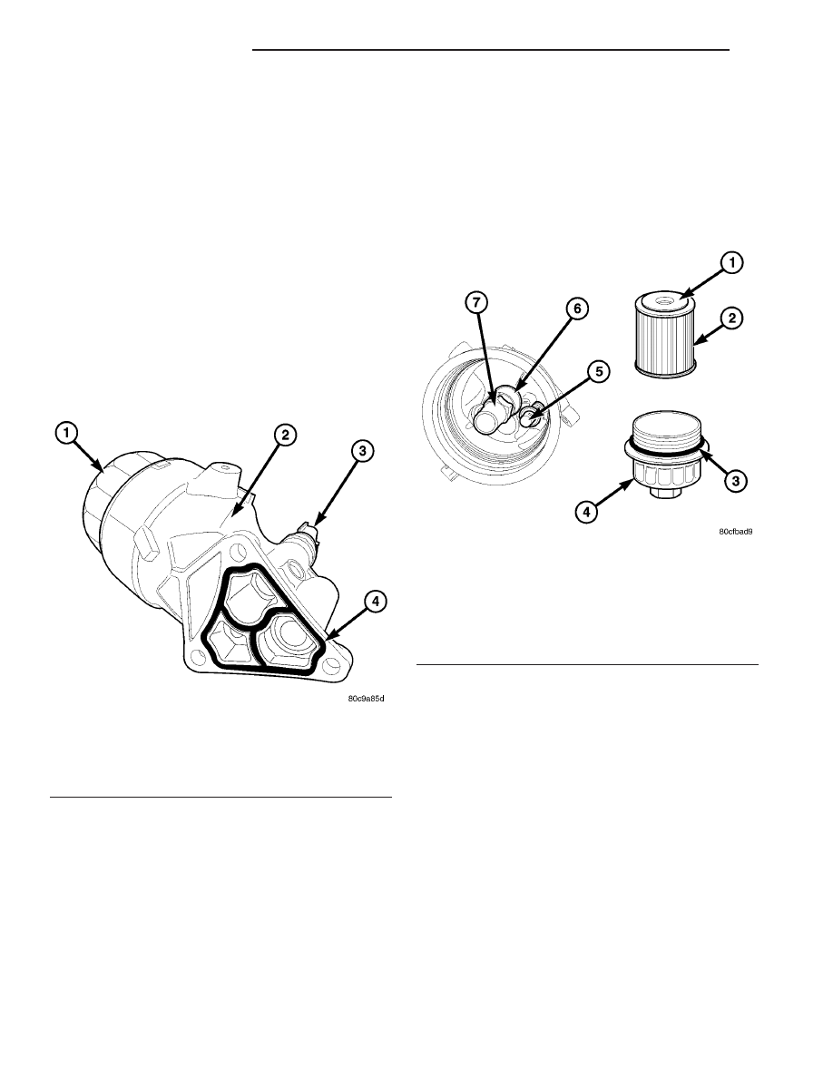
Fig. 93 Oil Filter Cartridge Housing

1 - OIL FILTER CAP
2 - OIL FILTER CARTRIDGE HOUSING
3 - OIL PRESSURE SWITCH
4 - SEAL

Fig. 94 Oil Filter Cartridge

1 - GROMMET
2 - OIL FILTER CARTRIDGE
3 - O-RING
4 - CAP
5 - DRAIN BACK VALVE
6 - CENTER POST
7 - STANDPIPE

9 - 60

ENGINE 1.6L SOHC

PT

LUBRICATION (Continued)

OIL FILTER CARTRIDGE
HOUSING

DESCRIPTION

The oil filter cartridge housing is attached to the

right side of the engine utilizing a seal between the
housing and engine block. The housing contains an
oil filter cartridge that cleans the engine oil coming
from the oil pump prior to it entering the main
engine oil gallery. The oil pressure switch is used to
provide the driver with engine oil pressure informa-
tion (Fig. 95).

Other components of the oil filter cartridge housing

(Fig. 95):

• By-Pass Valve: If the oil filter cartridge becomes

plugged, this valve opens allowing unfiltered oil to
enter the main engine oil gallery.

• Inlet Check Valve: This valve opens when engine

oil pressure pushes against it. After the engine is
shut off, the valve closes allowing oil to remain in the
oil filter cartridge housing.

• Drainback Valve: With the oil filter cartridge

installed, this valve is closed. As the oil filter cap and
oil filter cartridge are removed, the valve opens
allowing the reserve of oil in the cartridge housing to
drain back into the engine oil pan.

REMOVAL

(1) Raise vehicle on hoist.
(2) Disconnect oil pressure switch electrical con-

nector.

(3) Remove oil filter cartridge (Refer to 9 -

ENGINE/LUBRICATION/OIL FILTER CARTRIDGE
- REMOVAL).

(4) Remove fasteners securing oil filter cartridge

housing to engine block.

(5) Remove oil filter cartridge housing.

INSTALLATION

(1) Inspect and clean oil filter cartridge housing

sealing surfaces.

(2) Replace oil filter cartridge housing seal (Fig.

96)

(3) Install oil filter cartridge housing mounting

fasteners. Torque fasteners to 28 N·m (250 in. lbs.).

(4) Install

oil

filter

cartridge

(Refer

to

9

-

ENGINE/LUBRICATION/OIL FILTER CARTRIDGE
- INSTALLATION).

(5) Connect oil pressure switch electrical connec-

tor.

(6) Lower vehicle.
(7) Start engine. Check for leaks.
(8) Turn engine off. Check oil level. Fill oil to

proper level.

OIL PAN

REMOVAL

(1) Disconnect negative battery cable.
(2) Raise vehicle on hoist.
(3) Remove right front wheel.
(4) Remove accessory drive belt splash shield.
(5) Drain engine oil.

Fig. 95 Oil Filter Cartridge Housing

1 - OIL PRESSURE SWITCH
2 - BY-PASS VALVE
3 - INLET CHECK VALVE
4 - SEAL
5 - DRAINBACK VALVE

Fig. 96 Oil Filter Cartridge Housing

1 - OIL FILTER CAP
2 - OIL FILTER CARTRIDGE HOUSING
3 - OIL PRESSURE SWITCH
4 - SEAL

PT

ENGINE 1.6L SOHC

9 - 61

(6) Remove

air

conditioning

compressor

lower

bracket (Fig. 97).

(7) Remove bolt attaching lower torque strut to oil

pan bracket (Fig. 98).

(8) Remove clutch slave cylinder and reposition

(Fig. 99).

(9) Remove oil pan fasteners.
(10) Remove oil pan.

INSTALLATION

(1) Clean oil pan and all sealing surfaces.
(2) Position new oil pan gasket onto pan.
(3) Install oil pan (Fig. 100).

Fig. 97 Air Conditioning Compressor Lower Bracket

Fig. 98 Torque Strut Bracket

Fig. 99 Clutch Slave Cylinder

Fig. 100 Oil Pan and Gasket

9 - 62

ENGINE 1.6L SOHC

PT

OIL PAN (Continued)

(4) Install

oil

pan

fasteners

and

tighten

in

sequence (Fig. 101). Torque bolts to 31 N·m (275 in.
lbs.).

(5) Install the clutch slave cylinder (Fig. 99).
(6) Install

air

conditioning

compressor

lower

bracket (Fig. 98).

(7) Install accessory drive belt splash shield.
(8) Install right front wheel.
(9) Lower vehicle.
(10) Fill engine crankcase with the proper oil to

correct level. Refer to LUBRICATION AND MAIN-
TENANCE for oil capacity and type.

(11) Connect negative battery cable.

OIL PUMP

REMOVAL

(1) Remove timing chain cover (Refer to 9 -

ENGINE/VALVE TIMING/TIMING CHAIN COVER -
REMOVAL).

INSTALLATION

(1) Install

timing

chain

cover

(Refer

to

9

-

ENGINE/VALVE TIMING/TIMING CHAIN COVER -
INSTALLATION).

OIL PUMP PICK-UP

REMOVAL

(1) Remove oil pan (Refer to 9 - ENGINE/LUBRI-

CATION/OIL PAN - REMOVAL).

(2) Remove fasteners securing oil pump pick-up to

engine block (Fig. 102).

(3) Remove oil pump pick-up.

INSTALLATION

(1) Clean sealing surfaces.
(2) Replace o-ring (Fig. 102).
(3) Install oil pump pick-up. Torque fasteners to 12

N·m (105 in. lbs.).

(4) Install oil pan (Refer to 9 - ENGINE/LUBRI-

CATION/OIL PAN - INSTALLATION).

INTAKE MANIFOLD

REMOVAL

UPPER INTAKE MANIFOLD

(1) Disconnect negative battery cable.
(2) Disconnect throttle body air inlet hose and

purge solenoid vacuum hose from throttle body (Fig.
103).

(3) Disconnect PCV hose from upper intake mani-

fold (Fig. 103).

(4) Disconnect brake booster vacuum hose.
(5) Disconnect electronic throttle control motor

electrical connector.

(6) Remove upper intake manifold support bracket

fasteners (Fig. 103).

(7) Remove upper intake manifold fasteners (Fig.

103).

Fig. 101 Oil Pan Tightening Sequence

Fig. 102 Oil Pump Pick-up

1 - FASTENERS
2 - OIL PUMP PICK-UP
3 - O-RING

PT

ENGINE 1.6L SOHC

9 - 63

OIL PAN (Continued)


Content   ..  693  694  695  696   ..