Chrysler PT Cruiser. Manual - part 692


  Index      Chrysler     Chrysler PT Cruiser - service repair manual 2005 year


Search            


Content   ..  690  691  692  693   ..


Chrysler PT Cruiser. Manual - part 692


(17) Install the oil dipstick tube.
(18) Install the intake manifold (Refer to 9 -

ENGINE/MANIFOLDS/INTAKE

MANIFOLD

-

INSTALLATION).

(19) Install

the

timing

chain

(Refer

to

9

-

ENGINE/VALVE

TIMING/TIMING

BELT/CHAIN

AND SPROCKETS - INSTALLATION).

(20) Install the right engine mount bracket (Refer

to

9

-

ENGINE/ENGINE

MOUNTING/ENGINE

MOUNT BRACKET - INSTALLATION).

(21) Remove engine from repair stand and position

on Special Tools 6135 and 6710 Engine Dolly and
Cradle. Install safety straps around the engine to
cradle and tighten and lock them into position.

(22) Install the crankshaft rear oil seal. (Refer to 9

-

ENGINE/ENGINE

BLOCK/CRANKSHAFT

OIL

SEAL - REAR - INSTALLATION)

(23) Install flywheel. Install clutch and pressure

plate.

(24) Install the transaxle to engine.
(25) Install the engine assembly (Refer to 9 -

ENGINE - INSTALLATION).

CRANKSHAFT OIL SEAL -
FRONT

REMOVAL

(1) Remove timing chain cover (Refer to 9 -

ENGINE/VALVE TIMING/TIMING CHAIN COVER -
REMOVAL).

(2) Using a suitable tool, drive the front crank-

shaft oil seal out of the timing chain cover from the
back side.

INSTALLATION

(1) Install front crankshaft oil seal into timing

cover using Special Tool 6780.

(2) Install

timing

chain

cover

(Refer

to

9

-

ENGINE/VALVE TIMING/TIMING CHAIN COVER -
INSTALLATION).

CRANKSHAFT OIL SEAL -
REAR

REMOVAL

(1) Remove transaxle (Refer to 21 - TRANSMIS-

SION/TRANSAXLE/MANUAL - REMOVAL).

(2) Remove clutch and pressure plate.
(3) Remove flywheel.

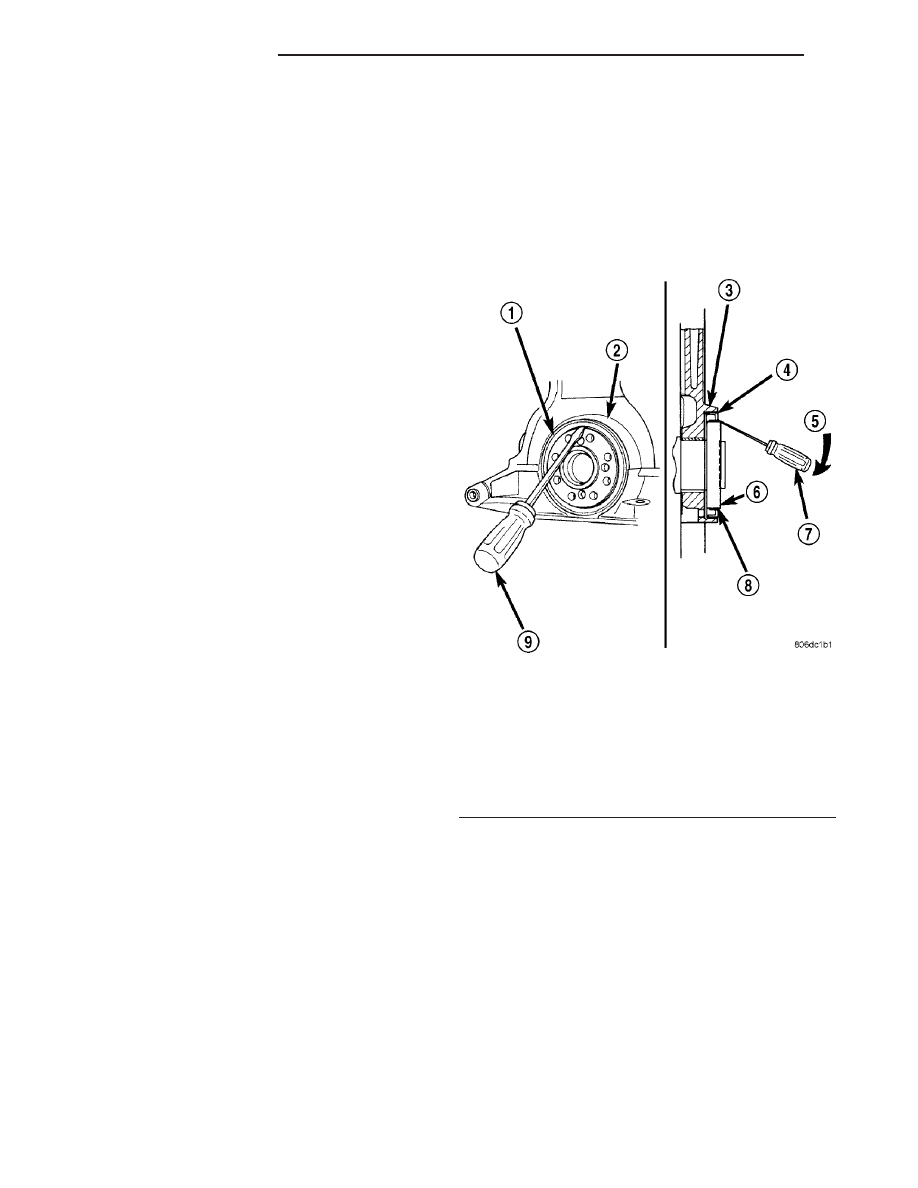
(4) Insert a 3/16 flat bladed screwdriver between

the dust lip and the metal case of the crankshaft
seal. Angle the screwdriver (Fig. 66) through the dust
lip against metal case of the seal. Pry out seal.

CAUTION: Do not permit the screwdriver blade to
contact crankshaft seal surface. Contact of the
screwdriver blade against crankshaft edge (cham-
fer) is permitted.

INSTALLATION

(1) Place Special Tool 6926-1 on crankshaft. This is

a pilot tool with a magnetic base (Fig. 67).

(2) Position seal over pilot tool. Pilot tool should

remain on crankshaft during installation of seal.
Ensure that the lip of the seal is facing towards the
crankcase during installation.

CAUTION: If the seal is driven into the block past
flush, an oil leak may result.

Fig. 66 Rear Crankshaft Oil Seal - Removal

1 - REAR CRANKSHAFT SEAL
2 - ENGINE BLOCK
3 - ENGINE BLOCK
4 - REAR CRANKSHAFT SEAL METAL CASE
5 - PRY IN THIS DIRECTION
6 - CRANKSHAFT
7 - SCREWDRIVER
8 - REAR CRANKSHAFT SEAL DUST LIP
9 - SCREWDRIVER

9 - 48

ENGINE 1.6L SOHC

PT

CRANKSHAFT (Continued)

(3) Drive the seal into the block using Special Tool

6926-2 and handle C-4171 until the tool bottoms out
against the block (Fig. 67).

(4) Install flywheel.
(5) Install clutch and pressure plate.
(6) Install transaxle (Refer to 21 - TRANSMIS-

SION/TRANSAXLE/MANUAL - INSTALLATION).

PISTON & CONNECTING ROD

DESCRIPTION

NOTE: The engine DOES NOT have provisions for a
free wheeling valve train. Non free wheeling valve
train means, in the event of a broken timing chain,
pistons will contact the valves.

The pistons are made of a cast aluminum alloy.

The pistons have pressed-in pins attached to forged
powdered metal connecting rods. The connecting rods
are a cracked cap design and are not repairable. Hex
head cap screws are used to provide alignment and
durability in the assembly. The pistons and connect-
ing rods are serviced as an assembly.

STANDARD PROCEDURE

CONNECTING ROD AND BEARING - FITTING

(1) Measure

connecting

rod

bearing

clearance

using Plastigage (Fig. 68). For more information on

use of Plastigage (Refer to 9 - ENGINE - STAN-
DARD PROCEDURE). Refer to Engine Specifications
for connecting rod specifications. (Refer to 9 -
ENGINE - SPECIFICATIONS)

CAUTION: Do not rotate crankshaft or the Plasti-
gage may be smeared.

NOTE: The rod bearing bolts should not be reused.

(2) Before installing NEW bolts, lubricate the

threads with clean engine oil.

(3) Install each bolt finger tight than alternately

torque each bolt to assemble the cap properly.

(4) Tighten the bolts to 26 N·m PLUS 1/4 turn (19

ft. lbs. PLUS 1/4 turn) Do not use a torque
wrench for last step.

(5) Using a feeler gauge, check connecting rod side

clearance (Fig. 69). Refer to Engine Specifications for
connecting rod specifications. (Refer to 9 - ENGINE -
SPECIFICATIONS)

Fig. 67 Rear Crankshaft Seal Installation

1 - REAR CRANKSHAFT OIL SEAL
2 - SPECIAL TOOL 6926-1 PILOT
3 - SPECIAL TOOL 6926-2 INSTALLER
4 - SPECIAL TOOL C-4171 DRIVE HANDLE

Fig. 68 Connecting Rod Bearing Clearance - Typical

Fig. 69 Measuring Connecting Rod Side Clearance -

Typical

PT

ENGINE 1.6L SOHC

9 - 49

CRANKSHAFT OIL SEAL - REAR (Continued)

CYLINDER BORE AND PISTON - FITTING

Piston and cylinder wall must be clean and dry.

Piston diameter should be measured 90 degrees to
piston pin about 14 mm (9/16 inch.) from the bottom
of the skirt as shown in (Fig. 71). Cylinder bores
should be measured halfway down the cylinder bore
and transverse (measurement location B) to the
engine crankshaft center line shown in (Fig. 70).
(Refer to 9 - ENGINE - SPECIFICATIONS) Correct
piston to bore clearance must be established in order
to assure quiet and economical operation.

NOTE: Pistons and cylinder bores should be mea-
sured at normal room temperature, 70°F (21°C).

REMOVAL

(1) Remove top ridge of cylinder bores with a reli-

able ridge reamer before removing pistons from cyl-
inder block. Be sure to keep tops of pistons
covered during this operation
.

CAUTION: DO NOT use a number stamp or a punch
to mark connecting rods. Damage to connecting
rod could occur.

(2) Using a permanent ink marker or scribe tool

mark the cylinder number on the side of the rod and
cap (Fig. 72) for identification.

(3) Pistons and connecting rods must be removed

from top of cylinder block. Rotate crankshaft so that
each connecting rod is centered in cylinder bore.

(4) Remove connecting rod cap bolts Do not use

old bolts if reinstalling connecting rod.

(5) To protect crankshaft journal and fractured rod

surfaces, install Special Tool 8388, connecting rod
guides onto connecting rod (Fig. 73). Carefully push
each piston and rod assembly out of cylinder bore.

CAUTION: Care must be taken not to damage the
fractured rod and cap joint surfaces, as engine
damage many occur.

(6) Remove Special Tool 8388, connecting rod

guides and re-install bearing cap on the mating rod.

Fig. 70 Checking Cylinder Bore - Typical

Fig. 71 Piston Measurement Location

1 - PISTON DIAMETER
2 - 14 mm (9/16 in.)

Fig. 72 Identify Connecting Rod to Cylinder -

Typical

9 - 50

ENGINE 1.6L SOHC

PT

PISTON & CONNECTING ROD (Continued)

NOTE: Piston and rods are serviced as an assem-
bly.

INSTALLATION

(1) Install piston rings on piston (Refer to 9 -

ENGINE/ENGINE

BLOCK/PISTON

RINGS

-

INSTALLATION).

(2) Rotate crankshaft so that the connecting rod

journal is on the center of the cylinder bore. Lubri-
cate connecting rod journal with clean engine oil.

(3) Install connecting rod bearing half onto con-

necting rod.

(4) Install Special Tool 8388 connecting rod guides

onto connecting rod (Fig. 74).

(5) Before installing pistons and connecting rod

assemblies into the bore, ensure the compression ring
gaps are staggered, and neither is in line with the oil
ring rail gap. Ensure the oil ring expander ends are
butted and the rail gaps are staggered.

(6) Immerse the piston head and rings in clean

engine oil, slide the ring compressor over the piston.
Be sure position of rings does not change dur-
ing this operation
.

(7) Compress piston rings.
(8) Install piston into cylinder making sure marks

on piston face toward front of engine (Fig. 74).

(9) Tap the piston down in cylinder bore, using a

hammer handle. At the same time, guide connecting
rod into position on connecting rod journal.

(10) Remove Special Tool 8388, connecting rod

guides.

(11) Install connecting rod lower bearing half and

cap. Install New bolts and tighten to 26 N·m (19 ft.
lbs.) plus 1/4 turn.

CAUTION: Do not use a torque wrench for the sec-
ond step.

PISTON RINGS

STANDARD PROCEDURE - PISTON RING -
FITTING

(1) Wipe cylinder bore clean. Insert ring and push

down with piston to ensure it is square in bore. The
ring gap measurement must be made with the ring
positioned below normal ring travel in the cylinder
bore. Check gap with feeler gauge (Fig. 75). For pis-
ton ring specifications (Refer to 9 - ENGINE - SPEC-
IFICATIONS).

Fig. 73 Connecting Rod Guides - Typical

1 - SPECIAL TOOL 8388 CONNECTING ROD GUIDES

Fig. 74 Piston/Connecting Rod Installation

1 - MARKINGS ON PISTON FACE FRONT OF ENGINE
2 - RING COMPRESSOR
3 - SPECIAL TOOL 8388 CONNECTING ROD GUIDES

Fig. 75 Piston Ring Gap - Typical

1 - FEELER GAUGE

PT

ENGINE 1.6L SOHC

9 - 51

PISTON & CONNECTING ROD (Continued)


Content   ..  690  691  692  693   ..