Chrysler PT Cruiser. Manual - part 522


  Index      Chrysler     Chrysler PT Cruiser - service repair manual 2005 year


Search            


Content   ..  520  521  522  523   ..


Chrysler PT Cruiser. Manual - part 522


(11) Working between seat back trim cover/cushion

and frame carefully unhook seat airbag studs from
nylon sleeve and slide airbag out of sleeve. Be careful
not to tear nylon sleeve as this will affect function of
airbag system.

CAUTION: Be certain not to tear the seat airbag
nylon sleeve during removal.

INSTALLATION

DEPLOYED SEAT AIRBAG

WARNING: DO NOT REPLACE A DEPLOYED SEAT
AIRBAG.

IF

THE

SEAT

AIRBAG

HAS

BEEN

DEPLOYED, THE ENTIRE SEAT BACK AND ALL
DAMAGED PARTS MUST BE REPLACED.

If the seat airbag was deployed, the entire seat

back must be replaced (Refer to 23 - BODY/SEATS/
SEAT BACK - INSTALLATION).

NONDEPLOYED SEAT AIRBAG

WARNING:

ONLY

REPLACE

A

NONDEPLOYED

SEAT AIRBAG IF FAULTY OR DEFECTIVE.

NOTE: The seat airbag connector must face down
(toward seat cushion) after installation.

(1) Carefully slide the side airbag in nylon sleeve

until mounting studs line up with holes provided in
nylon sleeve. Be careful not to tear nylon sleeve as
this will affect function of airbag system.

CAUTION: The side airbag must be inside the nylon
sleeve before installing retaining nuts. Failure to do
so will adversely affect the function of the side
impact airbag system.

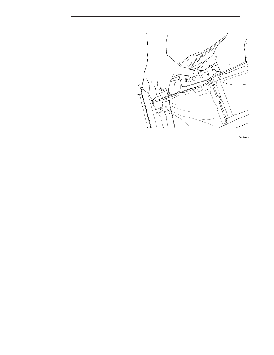
(2) Pull seat airbag and nylon sleeve assembly up

to line up mounting studs with holes provided in seat
back frame mounting bracket (Fig. 42). Install the
seat airbag retaining nuts. Torque to 10.7 N·m (94.7
in. lbs.).

(3) Position the upper seat back trim cover and

cushion over seat back frame.

(4) Connect the seat airbag electrical connector.

After initial connector is installed be certain the yel-
low locking tab is in the upper “locked” position.
Check to be certain connector cannot be removed
once yellow locking tab is positioned.

(5) Position seat back trim cover and install seat

back trim cover J-straps on the upper, lower and air-
bag side of seat back frame.

(6) Install the plastic back panel on the seat back

(Fig. 40). Install four screws in the upper mounting
location of the back cover.

CAUTION: Be certain plastic back panel is securely
installed on the seat back. Failure to do so will
adversely affect the side impact airbag system.

(7) Install the front seat in vehicle (Refer to 23 -

BODY/SEATS/SEAT - INSTALLATION).

WARNING: DO NOT CONNECT BATTERY NEGATIVE
CABLE YET (Refer to 8 - ELECTRICAL/RESTRAINTS
- DIAGNOSIS AND TESTING - AIRBAG SYSTEM).

(8) Close hood.
(9) Verify vehicle and system operation.

Fig. 42 INSTALLING SIDE AIRBAG INTO SEAT

BACK

8O - 24

RESTRAINTS

PT

SEAT AIRBAG (Continued)

SEAT BELT CINCH BAR

STANDARD PROCEDURE - SEAT BELT CINCH
BAR VERIFICATION TEST

WARNING: THE SEAT BELT CINCH BAR, CINCH
BAR COVER OR ANY OTHER SEAT BELT COMPO-
NENT MUST NEVER BE PAINTED. PAINT MAY
CHANGE THE WAY IN WHICH THE SEAT BELT
COMPONENTS PERFORM. FAILURE TO SO COULD
RESULT IN OCCUPANT PERSONAL INJURY OR
DEATH.

The latch plates of seat belts installed in certain

positions may be equipped with an automatic cinch-
ing feature (Fig. 43). The cinch bar mechanism is
designed to maintain the adjustment of the lap por-
tion of the belt webbing when the belt is buckled, but
allow the belt webbing to slide freely through the
latch plate for proper adjustment or storage when
the belt is not buckled. The following procedure will
verify proper seat belt cinch bar operation.

(1) Pull the suspect seat belt latch plate and web-

bing across the seat and insert the latch plate into
the buckle until it is fully engaged (Fig. 44).

(2) Place a paper clip or a small piece of tape on

the belt webbing on the lap belt side (not the shoul-

der belt side) of the latch plate as a reference mark
of the latch plate location.

(3) Release the seat belt latch plate from the

buckle and pull another 38 centimeters (15 inches) of
the belt webbing as measured from the latch plate
reference mark location through to the lap belt side
of the latch plate.

(4) Reinsert the latch plate into the buckle until it

is fully engaged.

(5) Firmly grasp the center of the lap belt web-

bing, then pull the belt webbing upwards and
towards the front of the vehicle while noting whether
any of the webbing pulls through the latch plate.

(6) The cinch bar should engage the belt webbing

and prevent it from being pulled through to the lap
belt side of the latch plate. If the cinching mecha-
nism is loose or fails to maintain proper lap belt
adjustment while the latch plate is buckled, a seat
belt cinch bar repair is required. (Refer to 8 - ELEC-
TRICAL/RESTRAINTS/SEAT BELT CINCH BAR -
REMOVAL).

Fig. 43 SEAT BELT CINCH BAR

1 - SHOULDER BELT SIDE
2 - CINCH BAR MECHANISM
3 - LAP BELT SIDE
4 - LATCH PLATE

Fig. 44 SEAT BELT CINCH BAR VERIFICATION

TEST

1 - SHOULDER BELT
2 - LATCH PLATE
3 - BUCKLE
4 - 38 CENTIMETERS (15 INCHES)
5 - REFERENCE MARK (TAPE OR PAPER CLIP)
6 - LAP BELT

PT

RESTRAINTS

8O - 25

REMOVAL

Before removing the cinch bar, verify that the

cinch bar holds the belt from sliding through the
latch

plate.

(Refer

to

8

-

ELECTRICAL/RE-

STRAINTS/SEAT BELT CINCH BAR - STANDARD
PROCEDURE - SEAT BELT CINCH BAR VERIFI-
CATION TEST). If the cinch bar components are not
present in the seat belt latch plate, go directly to the
installation procedure. (Refer to 8 - ELECTRICAL/
RESTRAINTS/SEAT BELT CINCH BAR - INSTAL-
LATION).

(1) Using

a

small

screwdriver

or

equivalent,

release the two cinch bar cover catches (Fig. 45).

(2) Remove and discard the cinch bar cover, the

cinch bar and the two small springs (Fig. 46).

INSTALLATION

WARNING: THE SEAT BELT CINCH BAR, CINCH
BAR COVER OR ANY OTHER SEAT BELT COMPO-
NENT MUST NEVER BE PAINTED. PAINT MAY
CHANGE THE WAY IN WHICH THE SEAT BELT
COMPONENTS PERFORM. FAILURE TO SO COULD
RESULT IN OCCUPANT PERSONAL INJURY OR
DEATH.

(1) Snap the new cinch bar onto the latch plate

bar by pushing up on the bottom edge of the cinch
bar. Be certain the new cinch bar is fully engaged
around the latch plate bar (Fig. 47).

(2) Install two of the three springs provided in the

repair package by positioning them over the dimples

on the latch plate bar, then into the second slot from
each end of the cinch bar (Fig. 48). The springs
might not be exactly perpendicular to the cinch bar.
This is acceptable.

Fig. 45 CINCH BAR COVER REMOVE

1 - SCREWDRIVER
2 - CINCH BAR COVER
3 - LATCH PLATE
4 - CATCH (2)

Fig. 46 CINCH BAR REMOVE

1 - CINCH BAR COVER
2 - LATCH PLATE BAR
3 - SPRING (2)
4 - CINCH BAR

Fig. 47 CINCH BAR INSTALL

1 - CINCH BAR
2 - LATCH PLATE BAR
3 - LATCH PLATE
4 - SEAT BELT WEBBING

8O - 26

RESTRAINTS

PT

SEAT BELT CINCH BAR (Continued)

(3) Align the cinch bar cover with the slots in the

cinch bar, then slide the cover forward and snap it
into place (Fig. 49). Be certain both cover catches are
fully engaged.

(4) Connect the seat belt latch plate to the buckle

and pull the webbing tight. Verify that the cinch bar

holds the belt from sliding through the latch plate.
(Refer

to

8

-

ELECTRICAL/RESTRAINTS/SEAT

BELT CINCH BAR - STANDARD PROCEDURE -
SEAT BELT CINCH BAR VERIFICATION TEST).

Fig. 48 CINCH BAR SPRINGS INSTALL

1 - SPRING (2)
2 - CINCH BAR
3 - LATCH PLATE BAR

Fig. 49 CINCH BAR COVER INSTALL

1 - CINCH BAR COVER
2 - CINCH BAR
3 - LATCH PLATE
4 - CATCH (2)

PT

RESTRAINTS

8O - 27

SEAT BELT CINCH BAR (Continued)


Content   ..  520  521  522  523   ..