Chrysler PT Cruiser. Manual - part 521


  Index      Chrysler     Chrysler PT Cruiser - service repair manual 2005 year


Search            


Content   ..  519  520  521  522   ..


Chrysler PT Cruiser. Manual - part 521


(5) Pull cushion cover back far enough to get at

the seat belt buckle anchor bolt.

(6) Remove the anchor bolt to the seat belt buckle

(Fig. 34) and remove from seat.

INSTALLATION

(1) Pull cushion cover back far enough to get at

the seat belt buckle anchor bolt.

(2) Position the seat belt buckle into position and

install the anchor bolt (Fig. 34).

(3) Install the two screws at the bottom of the

cushion cover (Fig. 33).

(4) Install the two screws at the side of the seat

cushion shield at the buckle area (Fig. 33).

(5) Return the rear seat to the unfolded position.

(6) Verify seat belt operation is free and not bind-

ing.

(7) Close door and decklid.

SATELLITE ACCELERATION
SENSOR

DESCRIPTION

Vehicles equipped with side impact airbags use two

impact or Satellite Acceleration Sensors (SAS). One
is located on each respective side body B-pillar.

The satellite acceleration sensors are electronic

accelerometers that sense the rate of vehicle deceler-
ation

and

when

combined

with

the

Occupant

Restraint Controller (ORC) accelerometer provides
verification of the direction and severity of a side
impact. Each sensor also contains an electronic com-
munication chip that allows the unit to communicate
the sensor status as well as sensor fault information
to the microprocessor in the ORC.

Refer to the appropriate wiring information and

Body Diagnostic Procedures manual for diagnosis
and testing.

OPERATION

The Satellite Acceleration Sensor (SAS) provides

verification of the direction and severity of the side
impact to the Occupant Restraint Controller (ORC).
The ORC controls both the right and the left right
side seat airbags. In the event of a side impact the
ORC will send an electronic signal to deploy the
appropriate seat airbag. The SAS periodically trans-
mit the acceleration data to the ORC by modulation
of the current on the power supply.

The accelerometer pulses are sent to a micropro-

cessor, which contains a decision algorithm. When an
impact is severe enough to require airbag protection,
the ORC microprocessor sends a signal to deploy the
side airbag that completes the electrical circuits to
the right or left side airbag. The ORC is calibrated
for the specific vehicle and reacts to the severity and
direction of the impact.

The ORC microprocessor continuously monitors all

of the passive restraint system electrical circuits to
determine the system readiness. If the ORC detects a
system fault, it sets a Diagnostic Trouble Code (DTC)
and controls the airbag warning indicator operation
accordingly. The side impact sensors receive battery
current and ground through dedicated driver and
passenger sensor signal and ground circuits from the
ORC. If the sensor is dropped it must be replaced.
Disconnect the battery or remove both airbag fuses
before servicing impact sensors.

Fig. 33 REAR SEAT CUSHION COVER/SHIELD

1 - REAR SEAT CUSHION COVER RETAINING SCREWS (5)

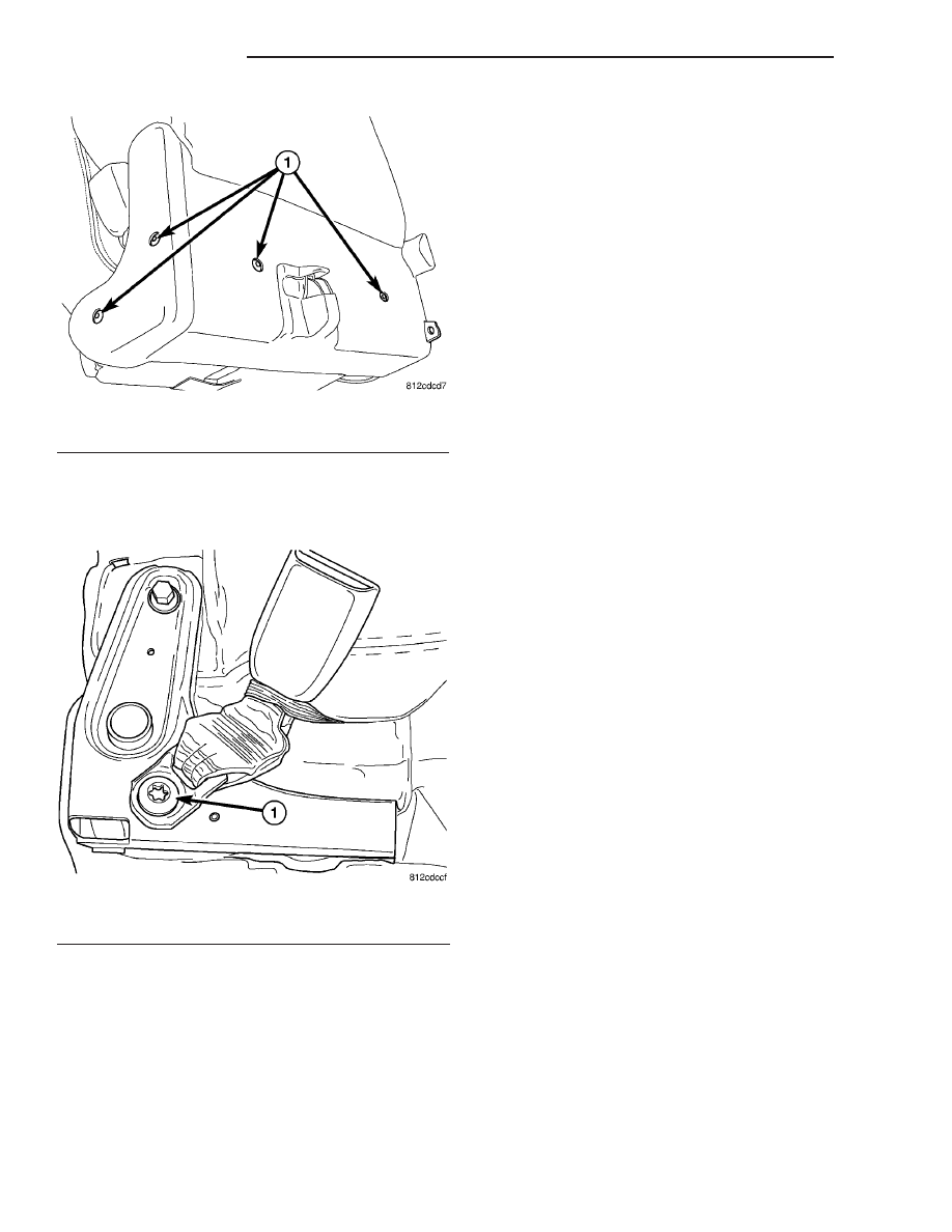
Fig. 34 SEAT BELT BUCKLE ANCHOR BOLT

1 - SEAT BELT BUCKLE ANCHOR BOLT (1)

8O - 20

RESTRAINTS

PT

REAR SEAT BELT BUCKLE - PT27 (Continued)

REMOVAL

(1) Disconnect and isolate the battery negative

cable remote terminal.

(2) Wait two minutes for the system reserve capac-

itor to discharge before servicing any airbag compo-
nents.

(3) Remove the lower B-pillar trim from the appro-

priate side of the vehicle. Refer to Body, Interior,
B-Pillar Lower Trim, Removal.

(4) Disconnect the satellite acceleration sensor

(SAS) electrical connector.

(5) Remove the SAS retaining screws and remove

the sensor from the vehicle.

INSTALLATION

(1) Position the satellite acceleration sensor (SAS)

in B-pillar (electrical connector facing forward in
vehicle) and install the retaining screws. Torque the
screws to 7 N·m (62 in. lbs.).

(2) Connect the SAS electrical connector.
(3) Install the lower B-pillar trim. Refer to Body,

Interior, B-Pillar Lower Trim, Installation.

WARNING: DO NOT CONNECT THE BATTERY NEG-
ATIVE CABLE REMOTE TERMINAL. REFER TO
ELECTRICAL, RESTRAINTS, DIAGNOSIS AND TEST-
ING - AIRBAG SYSTEM FIRST. FAILURE TO DO SO
COULD RESULT IN OCCUPANT PERSONAL INJURY
OR DEATH.

SATELLITE ACCELERATION
SENSOR - PT27

DESCRIPTION

Vehicles equipped with side impact airbags use two

impact or Satellite Acceleration Sensors (SAS) (Fig.
35). One is located on each respective side, just in
front of the B-pillar (Fig. 36).

The SAS’s are electronic accelerometers that sense

the rate of vehicle deceleration and when combined
with the Occupant Restraint Controller (ORC) accel-
erometer, provides verification of the direction and
severity of a side impact. Each sensor also contains
an electronic communication chip that allows the
unit to communicate the sensor status as well as sen-
sor fault information to the microprocessor in the
ORC.

For diagnosis and testing, use a scan tool and refer

to the appropriate body diagnostic information.

OPERATION

The Satellite Acceleration Sensor (SAS) provides

verification of the direction and severity of the side
impact to the Occupant Restraint Controller (ORC).
The ORC controls both the right and the left right
side seat airbags. In the event of a side impact the
ORC will send an electronic signal to deploy the
appropriate seat airbag. The SAS periodically trans-
mit the acceleration data to the ORC by modulation
of the current on the power supply.

The accelerometer pulses are sent to a micropro-

cessor, which contains a decision algorithm. When an
impact is severe enough to require airbag protection,
the ORC microprocessor sends a signal to deploy the
side airbag that completes the electrical circuits to
the right or left side airbag. The ORC is calibrated
for the specific vehicle and reacts to the severity and
direction of the impact.

The ORC microprocessor continuously monitors all

of the passive restraint system electrical circuits to
determine the system readiness. If the ORC detects a

Fig. 35 SATELLITE ACCELERATION SENSOR

Fig. 36 SAS LOCATION

1 - B-PILLAR
2 - SILL PLATE
3 - SATELLITE ACCELERATION SENSOR

PT

RESTRAINTS

8O - 21

SATELLITE ACCELERATION SENSOR (Continued)

system fault, it sets a Diagnostic Trouble Code (DTC)
and controls the airbag warning indicator operation
accordingly. The side impact sensors receive battery
current and ground through dedicated driver and
passenger sensor signal and ground circuits from the
ORC. If the sensor is dropped it must be replaced.

REMOVAL

(1) Open hood.
(2) Disconnect and isolate the battery negative

cable.

(3)

WARNING: Wait two minutes for the airbag system
reserve capacitor to discharge before beginning
any airbag system or component service. Failure to
do so may result in accidental airbag deployment,
personal injury or death.

(4) Remove the lower quarter trim from the appro-

priate side of the vehicle.

(5) Disconnect the Satellite Acceleration Sensor

(SAS) electrical connector (Fig. 37).

(6) Remove the SAS retaining screws and remove

the sensor from the vehicle (Fig. 37).

INSTALLATION

(1) Position the satellite acceleration sensor (SAS)

in position (Fig. 36).

(2) Install the retaining screws (Fig. 37). Torque

the screws to 8.5 N·m (75 in. lbs.).

(3) Connect the SAS electrical connector (Fig. 37).
(4) Install the quarter panel trim.

WARNING: Do not connect the battery negative
cable (Refer to 8 - ELECTRICAL/RESTRAINTS -
DIAGNOSIS AND TESTING - AIRBAG SYSTEM). Per-
sonal injury or death may result if the system test
is not performed first.

(5) Verify vehicle and system operation.
(6) Close hood.

SEAT AIRBAG

DESCRIPTION

The left and right seat airbags (Fig. 38) are located

in the outboard end of the front seat backs. The air-
bag contains a bag, an inflator (small canister of
highly compressed gas), and a mounting bracket. The
seat airbag cannot be repaired and must be replaced,
with the entire seat back assembly, if deployed or in
any way damaged.

OPERATION

When supplied with the proper electrical signal,

the inflator seals the hole in the airbag cushion so it
can discharge the compressed gas it contains directly
into the cushion. Upon deployment, the seat back
trim cover will tear open and allow the seat airbag to
fully deploy between the seat and the door.

Fig. 37 SATELLITE ACCELERATION SENSOR -

REMOVE/INSTALL

1 - SAS RETAINING SCREW
2 - SAS ELECTRICAL CONNECTOR
3 - BODY SIDE SILL PANEL
4 - SAS INDEXING PIN
5 - SATELLITE ACCELERATION SENSOR

Fig. 38 SEAT AIRBAG - TYPICAL

8O - 22

RESTRAINTS

PT

SATELLITE ACCELERATION SENSOR - PT27 (Continued)

REMOVAL

DEPLOYED SEAT AIRBAG

WARNING: DO NOT REPLACE A DEPLOYED SEAT
AIRBAG.

IF

THE

SEAT

AIRBAG

HAS

BEEN

DEPLOYED, THE ENTIRE SEAT BACK AND ALL
DAMAGED PARTS MUST BE REPLACED.

If the seat airbag was deployed, the entire seat

back must be replaced (Refer to 23 - BODY/SEATS/
SEAT BACK - REMOVAL).

NONDEPLOYED SEAT AIRBAG

WARNING:

ONLY

REPLACE

A

NONDEPLOYED

SEAT AIRBAG IF FAULTY OR DEFECTIVE.

(1) Position the front seat in the full forward posi-

tion.

(2) Open hood.
(3) Disconnect and isolate the battery negative

cable (Fig. 39).

(4) Wait two minutes for the system reserve capac-

itor to discharge before servicing any airbag compo-
nents.

(5) Remove front seat from vehicle (Refer to 23 -

BODY/SEATS/SEAT - REMOVAL).

(6) Remove plastic back panel from the seat back

(Fig. 40).

(7) Disengage seat back trim cover J-strap from

the upper, lower and airbag side of seat back.

(8) Disconnect the seat airbag electrical connector

(Fig. 41). Slide the yellow locking tab down to unlock.
Then with two fingers, push two side retaining tabs
in and pull connector straight from module.

(9) Remove the seat airbag retaining nuts.
(10) Grasp the upper airbag side of the seat back

trim cover and pull trim cover and cushion over top
of seat back frame. This will allow room to remove
seat airbag without damaging trim cover or cushion.

Fig. 39 BATTERY NEGATIVE CABLE - REMOVE/

INSTALL

Fig. 40 FRONT SEAT BACK REAR PANEL

1 - FRONT SEAT BACK REAR PANEL

Fig. 41 SEAT AIRBAG ELECTRICAL CONNECTOR

1 - SEAT AIRBAG NYLON SLEEVE
2 - SEAT AIRBAG
3 - SEAT AIRBAG ELECTRICAL CONNECTOR

PT

RESTRAINTS

8O - 23

SEAT AIRBAG (Continued)


Content   ..  519  520  521  522   ..