Chrysler PT Cruiser. Manual - part 512
When the switch is held in the top up position and
all four windows are fully up, the modules will lower
the respective front window 40mm, lower the respec-
tive rear window for 0.52 seconds (approx. 55mm)
and the driver window regulator module will ground
the top up relay control circuit. Once the top is back
up the windows will not raise automatically. When
the top switch is pressed in either position, the driver
window regulator module will ground the respective
relay control circuit for a maximum of 30 seconds.
The window regulator module monitors vehicle speed
and if the speed is over 15 mph. the top will not
operate. (Refer to 8 - ELECTRICAL/POWER WIN-
DOWS/WINDOW
REGULATOR
MODULE
-
DESCRIPTION) for additional information on the
window regulator module.
DIAGNOSIS AND TESTING
POWER TOP - CONVERTIBLE
Any diagnosis of the power top system should
begin with the use of a scan tool and the proper
Diagnostic Procedures Information. The scan tool can
provide confirmation that the Programmable Com-
munications Interface (PCI) data bus is functional,
that all of the electronic modules are sending and
receiving the proper messages on the PCI data bus,
and that the power top motor is being sent the
proper hard wired output by the driver window reg-
ulator module.
Refer to the appropriate diagnostic informa-
tion.
MOTOR/HYDRAULIC PUMP
ASSEMBLY
DIAGNOSIS AND TESTING
MOTOR/HYDRAULIC PUMP ASSEMBLY
Any diagnosis of the power top system should
begin with the use of a scan tool and the proper
Diagnostic Procedures Information. The scan tool can
provide confirmation that the Programmable Com-
munications Interface (PCI) data bus is functional,
that all of the electronic modules are sending and
receiving the proper messages on the PCI data bus,
and that the power top motor is being sent the
proper hard wired output by the driver window reg-
ulator module.
If the power top is completely inoperative and the
motor/hydraulic pump assembly is suspect, perform
the following:
(1) Disconnect and isolate the battery negative
cable.
(2) Remove the rear seat back, (Refer to 23 -
BODY/SEATS/SEAT BACK - REMOVAL).
(3) Remove the well liner/carpet from the power
top well.
(4) Remove the foam pump cover from over the
motor/hydraulic pump.
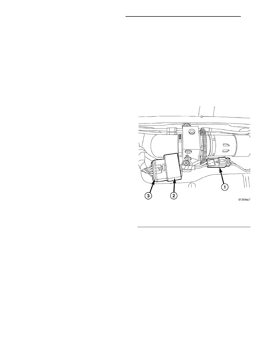
(5) Disconnect the motor/hydraulic pump wire har-
ness connector (Fig. 2).
(6) Reconnect the battery negative cable.
(7) Insert a 12V test light between the two connec-
tor terminals of the motor/hydraulic pump wire har-
ness connector.
(8) With the ignition in the “RUN” position, oper-
ate the power top in both directions while observing
the test light. The light should illuminate in both
directions. If OK, replace the inoperative motor/hy-
draulic pump assembly, (Refer to 8 - ELECTRICAL/
POWER TOP/MOTOR - REMOVAL). If not OK, use a
scan tool and the proper Diagnostic Procedures Infor-
mation to complete diagnosis of the power top sys-
tem.
Fig. 2 MOTOR/HYDRAULIC PUMP ASSEMBLY
1 - MOTOR/HYDRAULIC PUMP CONNECTOR
2 - MOTOR/HYDRAULIC PUMP RELAY
3 - MOTOR/HYDRAULIC PUMP RELAY CONNECTOR
8N - 18
POWER TOP - CONVERTIBLE - PT27
PT
POWER TOP - CONVERTIBLE - PT27 (Continued)