Chrysler PT Cruiser. Manual - part 467
ANTENNA BODY & CABLE
DESCRIPTION
The antenna body and cable are secured below the
fender panel by the antenna cap nut through a
mounting hole in the side of the right front fender.
The primary coaxial antenna cable is then routed
beneath the fender sheet metal and through a entry
hole in the right cowl side panel into the interior of
the vehicle. Inside the vehicle, the primary coaxial
cable is connected to a secondary instrument panel
antenna coaxial cable with an in-line connector that
is located behind the right end of the instrument
panel. The secondary coaxial cable is then routed
behind the instrument panel to the back of the radio.
OPERATION
The antenna body and cable connects the antenna
mast to the radio. The radio antenna is an electro-
magnetic circuit component used to capture radio fre-
quency
signals
that
are
broadcast
by
local
commercial radio stations in both the Amplitude
Modulating (AM) and Frequency Modulating (FM)
frequency ranges. These electromagnetic radio fre-
quency signals induce small electrical modulations
into the antenna as they move past the mast. The
antenna body transfers the weak electromagnetic
radio waves induced into the rigid antenna mast into
the center conductor of the flexible primary antenna
coaxial cable. The braided outer shield of the
antenna coaxial cable is grounded through both the
antenna body and the radio chassis, effectively
shielding the radio waves as they are conducted to
the radio. The radio then tunes and amplifies the
weak radio signals into stronger electrical signals in
order to operate the audio system speakers.
DIAGNOSIS AND TESTING - ANTENNA BODY
AND CABLE
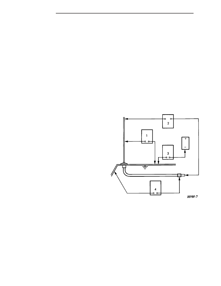
The following four tests are used to diagnose the
antenna with an ohmmeter:
• Test 1 - Mast to ground test
• Test 2 - Tip-of-mast to tip-of-conductor test
• Test 3 - Body ground to battery ground test
• Test 4 - Body ground to antenna coaxial cable
shield test.
WARNING:
DISABLE
THE
AIRBAG
SYSTEM
BEFORE ATTEMPTING ANY STEERING WHEEL,
STEERING COLUMN, SEAT BELT TENSIONER, SIDE
AIRBAG, OR INSTRUMENT PANEL COMPONENT
DIAGNOSIS OR SERVICE. DISCONNECT AND ISO-
LATE THE BATTERY NEGATIVE (GROUND) CABLE,
THEN WAIT TWO MINUTES FOR THE AIRBAG SYS-
TEM CAPACITOR TO DISCHARGE BEFORE PER-
FORMING FURTHER DIAGNOSIS OR SERVICE. THIS
IS THE ONLY SURE WAY TO DISABLE THE AIRBAG
SYSTEM. FAILURE TO TAKE THE PROPER PRE-
CAUTIONS COULD RESULT IN ACCIDENTAL AIR-
BAG DEPLOYMENT AND POSSIBLE PERSONAL
INJURY.
The ohmmeter test lead connections for each test
are shown in the illustration (Fig. 1).
NOTE: This model has a two-piece antenna coaxial
cable. Tests 2 and 4 must be conducted in two
steps to isolate an antenna cable problem. First,
test the primary antenna cable (integral to the
antenna body and cable) from the coaxial cable
connector under the right end of the instrument
panel near the right cowl side inner panel to the
antenna body. Then, test the secondary antenna
cable (instrument panel antenna cable) from the
coaxial cable connector under the right end of the
instrument panel near the right cowl side inner
panel to the coaxial cable connector at the radio.
TEST 1
Test 1 determines if the antenna mast is insulated
from ground. Proceed as follows:
(1) Disconnect and isolate the antenna coaxial
cable connector under the right end of the instru-
ment panel near the right cowl side inner panel.
(2) Touch one ohmmeter test lead to the tip of the
antenna mast (below tip if ball tip is plastic). Touch
the other test lead to the antenna cap nut. Check the
ohmmeter reading for continuity.
(3) There should be no continuity. If OK, go to Test
2. If not OK, replace the faulty antenna body and
cable.
Fig. 1 ANTENNA TEST - TYPICAL
8A - 4
AUDIO/VIDEO
PT