Chrysler PT Cruiser. Manual - part 438


  Index      Chrysler     Chrysler PT Cruiser - service repair manual 2005 year


Search            


Content   ..  436  437  438  439   ..


Chrysler PT Cruiser. Manual - part 438


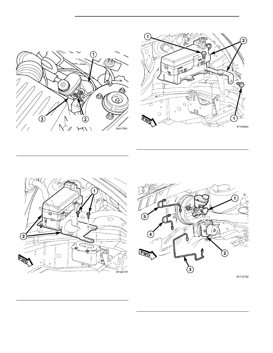
(4) Disconnect the vehicle wiring harness connec-

tor from the brake fluid level switch in the master
cylinder brake fluid reservoir (Fig. 29).

(5) Remove the two bolts fastening the power dis-

tribution center mounting bracket in place (Fig. 30)
(Fig. 31).

(6) Lift the power distribution center and mount-

ing bracket up and move it to the driver side.

(7) Clean the area around where brake tubes

attach to the ICU hydraulic control unit (HCU) using

a suitable brake cleaner such as Mopar

t Brake Parts

Cleaner or equivalent.

(8) Remove the primary and secondary brake

tubes coming from the master cylinder at the HCU
(Fig. 32) (Fig. 33).

(9) Disconnect the chassis brake tubes at the HCU

(Fig. 32) (Fig. 33) (Fig. 34).

Fig. 29 Master Cylinder

1 - POWER BRAKE BOOSTER
2 - BRAKE FLUID LEVEL SWITCH
3 - MASTER CYLINDER

Fig. 30 PDC With Bracket Mounting - Non-Turbo

Engine

1 - MOUNTING BOLTS
2 - PDC AND MOUNTING BRACKET

Fig. 31 PDC With Bracket Mounting - Turbo Engine

1 - MOUNTING BOLTS
2 - PDC AND MOUNTING BRACKET

Fig. 32 Primary And Secondary Brake Tubes To ICU

1 - MASTER CYLINDER
2 - HCU
3 - LEFT FRONT CHASSIS BRAKE TUBE
4 - SECONDARY BRAKE TUBE
5 - PRIMARY BRAKE TUBE

5 - 104

BRAKES - ABS

PT

INTEGRATED CONTROL UNIT (ICU) - MK25E (Continued)

(10) Disconnect the 47-way connector from the

antilock brake module (ABM) by depressing the tabs
on each side of the connector cover (Fig. 35), then
pulling outward and upward on the lower half of the
cover until it locks into position pointing straight
outward. The connector can then be pulled straight
outward off the ABM (Fig. 36).

Fig. 33 RHD Primary & Secondary Brake Tubes To

ICU

1 - MASTER CYLINDER
2 - SECONDARY BRAKE TUBE
3 - PRIMARY BRAKE TUBE
4 - HCU
5 - LEFT FRONT CHASSIS BRAKE TUBE

Fig. 34 Chassis Brake Tubes At ICU

1 - RIGHT FRONT CHASSIS BRAKE TUBE
2 - LEFT REAR CHASSIS BRAKE TUBE
3 - RIGHT REAR CHASSIS BRAKE TUBE
4 - HCU

Fig. 35 ABM Connector Release Tabs

Fig. 36 Wiring Harness Connector At ABM

1 - ABM (PART OF ICU)
2 - WIRING HARNESS CONNECTOR

PT

BRAKES - ABS

5 - 105

INTEGRATED CONTROL UNIT (ICU) - MK25E (Continued)

(11) Raise and support the vehicle. (Refer to

LUBRICATION

&

MAINTENANCE/HOISTING

-

STANDARD PROCEDURE)

(12) Remove the two rear mounting screws attach-

ing the ICU mounting bracket to the body (Fig. 37).

(13) Lower the vehicle.
(14) Remove the front mounting screw attaching

the ICU mounting bracket to the body (Fig. 37).

(15) Lift the ICU and mounting bracket from the

vehicle.

(16) To separate the ABM from the HCU, (Refer to

5

-

BRAKES/HYDRAULIC/MECHANICAL/ICU

(INTEGRATED CONTROL UNIT) - DISASSEMBLY).

DISASSEMBLY

(1) If the mounting bracket needs to be removed

from the ICU, remove the single mounting bolt (Fig.
38), then slide the ICU’s mounting pins out of the
grommets in the bracket. Remove the mounting pins
from the ICU as necessary.

(2) If not equipped with traction control, remove

the three screws attaching the ABM to the HCU (Fig.
39).

(3) If equipped with traction control, remove the

four screws attaching the ABM to the HCU (Fig. 40).

(4) Separate the ABM from the HCU (Fig. 41).

ASSEMBLY

(1) Clean any debris off the mating surfaces of the

HCU and ABM.

CAUTION: When installing new O-rings or solenoid
valve stem seals, do not use any type of lubricant.

(2) If the seals on the components are not new,

they must be replaced. Each of the solenoid valve
stem seals must be replaced (Fig. 42); do not reuse
solenoid valve stem seals
. The pump/motor con-
nector O-ring should also be replaced if not new (Fig.
43).

Fig. 37 ICU Mounting

1 - BODY FRAME RAIL
2 - FRONT MOUNTING SCREW
3 - ICU MOUNTING BRACKET
4 - REAR MOUNTING SCREWS

Fig. 38 ICU Mounting Bolt

1 - ICU
2 - MOUNTING BOLT
3 - MOUNTING BRACKET

Fig. 39 ABM Mounting Screws - Without Traction

Control

1 - MOUNTING SCREWS
2 - ABM

5 - 106

BRAKES - ABS

PT

INTEGRATED CONTROL UNIT (ICU) - MK25E (Continued)

(3) Align components and install the ABM on the

HCU (Fig. 41).

(4) If not equipped with traction control, install

the three screws attaching the ABM to the HCU (Fig.
39). Tighten the mounting screws to 2 N·m (17 in.
lbs.) torque.

(5) If equipped with traction control, install the

four screws attaching the ABM to the HCU (Fig. 40).

Tighten the mounting screws to 2 N·m (17 in. lbs.)
torque.

(6) If the mounting bracket needs to be installed,

install the mounting pins in the ICU as necessary
and tighten to 11 N·m (97 in. lbs.) torque. Insert the
mounting pins into the grommets mounted in the
bracket, then install the single mounting bolt (Fig.
38). Tighten the mounting bolt to 11 N·m (97 in. lbs.)
torque.

Fig. 40 ABM Mounting Screws - With Traction

Control

1 - MOUNTING SCREWS
2 - ABM

Fig. 41 ABM Assembly To HCU

1 - ABM
2 - HCU
3 - SOLENOID VALVE STEM

Fig. 42 Solenoid Valve Seal

1 - SEAL
2 - SOLENOID VALVE STEM

Fig. 43 Internal Pump Connector O-Ring

1 - O-RING
2 - O-RING MOUNTING GROOVE

PT

BRAKES - ABS

5 - 107

INTEGRATED CONTROL UNIT (ICU) - MK25E (Continued)


Content   ..  436  437  438  439   ..