Chrysler New Yorker. Manual - part 111
To set the variance:
• Turn ignition key ON
• Press the C/T button to select the Compass/Tem-
perature display
• Press and hold RESET button; the VAR symbol
should come on in about 5 seconds.
• The OTIS will display the variance zone and the
word VAR.
• Press STEP button to select the desired zone.
• Press RESET button to set the new variance
zone and resume normal operation.
TRAINING THE UNIVERSAL TRANSMITTER
To train the universal transmitter, refer to proce-
dures outlined in the Owner’s Manual or proper Body
Diagnostics Procedures Manual.
UNIVERSAL TRANSMITTER CHANNEL STATUS
The Universal Transmitter feature has three inde-
pendent RF channels. The DRB can be used to check
each channel. For the necessary message set to check
the universal transmitter, use DRB scan tool and
proper Body Diagnostic Procedures Manual.
REMOVAL AND INSTALLATION
AMBIENT TEMPERATURE SENSOR
REMOVAL
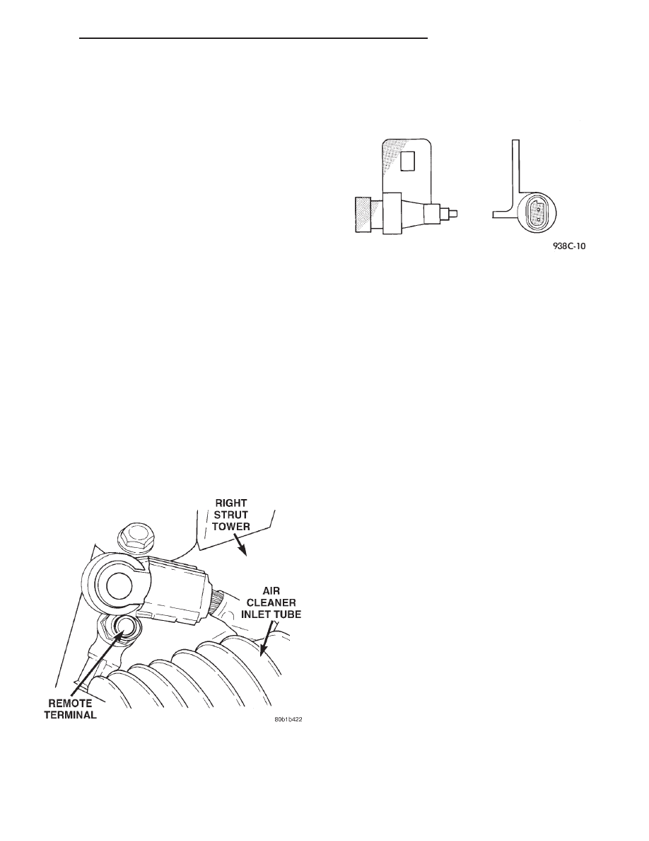
(1) Open hood, disconnect and isolate the negative
battery cable remote terminal from the remote bat-
tery post (Fig. 5).
(2) Raise and support vehicle on safety stands.
(3) From behind front bumper fascia, remove
screw attaching sensor to radiator closure panel (Fig.
6).
INSTALLATION
For installation, reverse the above procedures.
BASE UNIT
REMOVAL
(1) Open hood, disconnect and isolate the negative
battery cable remote terminal from the remote bat-
tery post (Fig. 5).
(2) Grasp the both outer sides and pull downward
to disconnect the retaining clips.
(3) Disconnect wire connector and lower the unit.
(4) Remove console from vehicle.
INSTALLATION
For installation, reverse the above procedures.
MAP LAMP
REMOVAL
(1) Open hood, disconnect and isolate the negative
battery cable remote terminal from the remote bat-
tery post (Fig. 5).
(2) Remove overhead console, refer to Console
Removal and Installation procedures in this section.
(3) Remove lamp socket from mounting.
(4) Remove lamp(s). Replace as necessary.
INSTALLATION
For installation, reverse the above procedures.
MINI CONSOLE
REMOVAL
(1) Remove screw from windshield side of console.
(2) Grasp the front of console and pull downward
to disconnect the retaining clips.
(3) Disconnect wire connectors and lower the con-
sole.
Fig. 5 Negative Battery Cable Remote Terminal
Fig. 6 Ambient Temperature Sensor
300M
OVERHEAD CONSOLE
8V - 5
SERVICE PROCEDURES (Continued)