Chrysler New Yorker. Manual - part 82


  Index      Chrysler     Chrysler New Yorker - service repair manual 1997-1999 year


Search            


Content   ..  80  81  82  83   ..


Chrysler New Yorker. Manual - part 82


WINDSHIELD WASHERS NOZZLES

RIGHT HOOD NOZZLE

REMOVAL

(1) Remove the underhood silencer pad clips (only

along the rear of hood).

(2) Carefully pull silencer pad away from the hood.
(3) Disconnect the right nozzle hose at the “Y”

connector.

(4) Disconnect hose from the two hose clips.
(5) Using a long and narrow straight screwdriver,

position tip against nozzle retention tab and apply
sufficient force to disconnect nozzle from hood.

(6) Pull nozzle and hose away from outside of

hood.

(7) Disconnect right hose clips from hood (if

required).

INSTALLATION

(1) For installation, reverse the above procedures.
(2) During assembly of nozzle and hose to hood,

gently pull on hose to assure hose is not kinked and
nozzle body is securely snapped into position.

(3) After connecting hose to “Y” connector, check

for proper system function and to assure leak free
connections by actuating the washer system switch
from inside of vehicle.

LEFT HOOD NOZZLE

REMOVAL

(1) Remove underhood silencer pad clips only

along left rear of hood.

(2) Carefully pull silencer pad away from hood.
(3) Disconnect left nozzle hose at “Y” connector.
(4) Using a long and narrow straight screwdriver,

position tip against nozzle retention tab and apply
sufficient force to disconnect nozzle from hood.

(5) Pull nozzle and hose away from outside of

hood.

INSTALLATION

(1) For installation, reverse the above procedures.
(2) During assembly of nozzle and hose to hood,

gently pull on hose to assure hose is not kinked and
nozzle body is securely snapped into position.

(3) After connecting hose to “Y” connector, check

for proper system function and to assure leak free
connections by actuating the washer system switch
from inside of vehicle.

WASHER RESERVOIR

REMOVAL

(1) Open hood and disconnect the negative battery

cable remote terminal from the remote battery post
(Fig. 4).

(2) Hoist vehicle.
(3) Remove front fascia as necessary (left side only

and use a 2x4 to prop left edge of fascia away from
body). Refer to Group 23, Body for Removal and
Installation procedures.

(4) Disconnect the wire connectors from the reser-

voir pump and float sensor.

(5) Disconnect the washer hose and block the liq-

uid outlet to prevent the liquid from running out of
the reservoir.

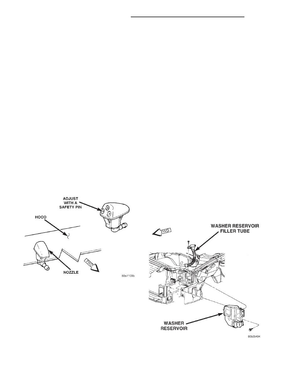
(6) Reach up behind the washer reservoir and pull

the filler tube off the rear of the reservoir.

(7) Remove four mounting bolts to washer reser-

voir (Fig. 7).

Fig. 6 Windshield Washer Nozzle

Fig. 7 Washer Reservoir Removal

8K - 14

WINDSHIELD WIPERS AND WASHERS

300M

REMOVAL AND INSTALLATION (Continued)

(8) Remove washer reservoir from vehicle.
(9) Transfer fluid level sensor, pump, and washer

fluid to new reservoir (Fig. 8).

INSTALLATION

(1) Connect washer hose, filler tube, and wire con-

nectors to reservoir.

(2) Install reservoir retaining bolts. Torque bolts to

80 to 124 in. lbs. (9 to 14 N·m).

(3) Reconnect the negative battery cable remote

terminal.

WASHER RESERVOIR FILLER TUBE

REMOVAL

(1) Open hood and disconnect the negative battery

cable remote terminal from the remote battery post
(Fig. 4).

(2) Hoist vehicle.
(3) Remove front fascia as necessary (left side only

and use a 2x4 to prop left edge of fascia away from
body). Refer to Group 23, Body for Removal and
Installation procedures.

(4) Reach up behind the washer reservoir and pull

the filler tube off the rear of the reservoir.

(5) Remove one screw attaching washer reservoir

filler tube to upper radiator support (Fig. 9).

(6) Pull filler tube and hose up through left fender

and remove.

INSTALLATION

For installation, reverse the above procedures.

NOTE: Replace/refill washer fluid after filler tube
replacement.

WASHER RESERVOIR PUMP

REMOVAL

(1) Open hood and disconnect the negative battery

cable remote terminal from the remote battery post
(Fig. 4).

(2) Hoist vehicle.
(3) Remove front fascia as necessary (left side only

and use a 2x4 to prop left edge of fascia away from
body). Refer to Group 23, Body for Removal and
Installation procedures.

(4) Disconnect the wire connectors from the reser-

voir pump.

(5) Gently pry pump away from reservoir and out

of grommet. Care must be taken not to puncture res-
ervoir (Fig. 8).

(6) Remove rubber grommet from reservoir and

throw away.

INSTALLATION

For installation, reverse the above procedures. Use

new rubber grommet with new pump. Assure pump
is fully seated into reservoir.

NOTE: Replace/refill washer fluid after reservoir
pump replacement.

Fig. 8 Washer Reservoir

Fig. 9 Washer Reservoir Filler Tube

300M

WINDSHIELD WIPERS AND WASHERS

8K - 15

REMOVAL AND INSTALLATION (Continued)

WIPER ARM AND BLADE

REMOVAL

(1) Cycle the wiper arm/blades into PARK position

and turn ignition OFF.

(2) Using a trim stick (special tool #C-4755), gently

pry up on the wiper arm retaining nut cap and
remove.

(3) Remove the retaining nut from the wiper arm

pivot.

(4) Lift wiper arm to raise blade off glass and

remove the arm from the pivot using a rocking
motion and remove from vehicle.

INSTALLATION

For installation, reverse the above procedures.
Refer to Wiper Arm Adjustment in this section for

adjustment procedures.

WIPER BLADE

REMOVAL

(1) Lift wiper arm to raise blade off glass.
(2) Remove blade assembly from arm by pushing

release tab under arm tip and slide blade away from
arm tip (Fig. 10) and (Fig. 11). The vertebra is curved
on the right blade only. Install with the curve match-
ing the shape of the windshield.

(3) Gently place wiper arm tip on glass surface.

INSTALLATION

For installation reverse the above procedures.

NOTE: The vertebra is curved on right side only.
Install with curve matching shape of windshield.

WIPER BLADE ELEMENT

REMOVAL

(1) Remove wiping element from blade assembly

by grasping and pulling stopper of blade element out
of end claw together with vertebra (metal rails).

(2) Remove wiping element and vertebra by sliding

them out of claws.

(3) Remove vertebra from wiping element.

INSTALLATION
For installation reverse the above
procedures.

(1) Install right blade element vertebra to match

the shape of the windshield. Install vertebra with
curve down.

(2) Install left blade element vertebra flat.
(3) Check that blade element and vertebra are

through all the claws and the final claw is locked in
the stopper. Assure element locked end is closest to
wiper system pivot.

WIPER FRAME ASSEMBLY

REMOVAL

(1) Open hood and disconnect the negative battery

cable remote terminal from the remote battery post
(Fig. 4).

(2) Remove driver and passenger side wiper arms.

Refer to Wiper Arm Removal and Installation proce-
dures in this section.

(3) Remove nine screws to cowl screen panel. Refer

to Group 23, Body for Removal and Installation pro-
cedures.

(4) Remove wiper module mounting bolt located on

top of the tower to tower beam.

(5) Remove eight bolts to Tower to Tower (crosscar)

support (Fig. 13). Refer to Group 23, Body for
Removal and Installation procedures.

Fig. 10 Wiper Blade and Element

Fig. 11 Remove Blade from Arm

Fig. 12 Wiper Blade and Element

8K - 16

WINDSHIELD WIPERS AND WASHERS

300M

REMOVAL AND INSTALLATION (Continued)

(6) Remove three retaining bolts to windshield

wiper module (Fig. 14).

(7) Lift wiper module away from vehicle body.
(8) Disconnect one wire connector.
(9) Remove windshield wiper module from vehicle.

TRANSFER PARTS

(1) Transfer wiper module grommets to new mod-

ule assembly (Fig. 15).

(2) Remove one nut to crank arm and remove from

motor (Fig. 17).

(3) Remove three retaining bolts from wiper motor

(Fig. 17).

(4) Remove wiper motor from wiper module assem-

bly. Install onto new wiper module assembly. Refer to

Wiper Motor Removal and Installation procedures in
this section.

INSTALLATION

For installation, reverse the above procedures.
(1) Start rear outboard screw first, rear inboard

screw second, and forward outboard screw last.

(2) Start all module mounting screws and bolt by

hand before torquing to specifications.

(3) Assur wiper module pivots are in “PARK” posi-

tion cycling the switch “ON” and “OFF” with engine
off prior to installing arms and blades.

CAUTION: KEEP

HANDS

CLEAR

OF

CYCLING

WIPER MODULE LINKAGE.

WIPER LINK ARMS

There a two servicable link assemblies in the wiper

module. The Master Link connects the motor output
crank to the drivers side pivot. The Slave link con-
nects the driver side pivot to the passenger side
pivot. To service these links, remove the wiper mod-
ule from the vehicle.

The wiper module mounting grommets can be ser-

viced anytime the module is removed from the vehi-
cle. Replace module mounting grommets if they are
broken, cracked, deteriorated, or defective.

REMOVAL

(1) Open hood and disconnect the negative battery

cable remote terminal from the remote battery post
(Fig. 4).

(2) Remove wiper module from vehicle. Refer to

Wiper Module Removal and Installation in this sec-
tion.

(3) Disconnect wiper module slave link from pivot

levers by carefully using a ball and socket wedge. Do
not damage ball and socket or seal when using
wedge.

(4) Disconnect wiper module master link from

pivot lever and motor crank by carefully using a ball
and socket wedge. Do not damage ball and socket or
seal when using wedge.

(5) Remove module linkage mounting grommets.

Fig. 13 Tower to Tower Support Removal

Fig. 14 Wiper Module Retaining Bolts

Fig. 15 Wiper Frame Grommets

Fig. 16 Wiper Link Arms

300M

WINDSHIELD WIPERS AND WASHERS

8K - 17

REMOVAL AND INSTALLATION (Continued)


Content   ..  80  81  82  83   ..