Chrysler New Yorker. Manual - part 75
 

  Index      Chrysler     Chrysler New Yorker - service repair manual 1997-1999 year


Search            


Content   ..  73  74  75  76   ..


Chrysler New Yorker. Manual - part 75


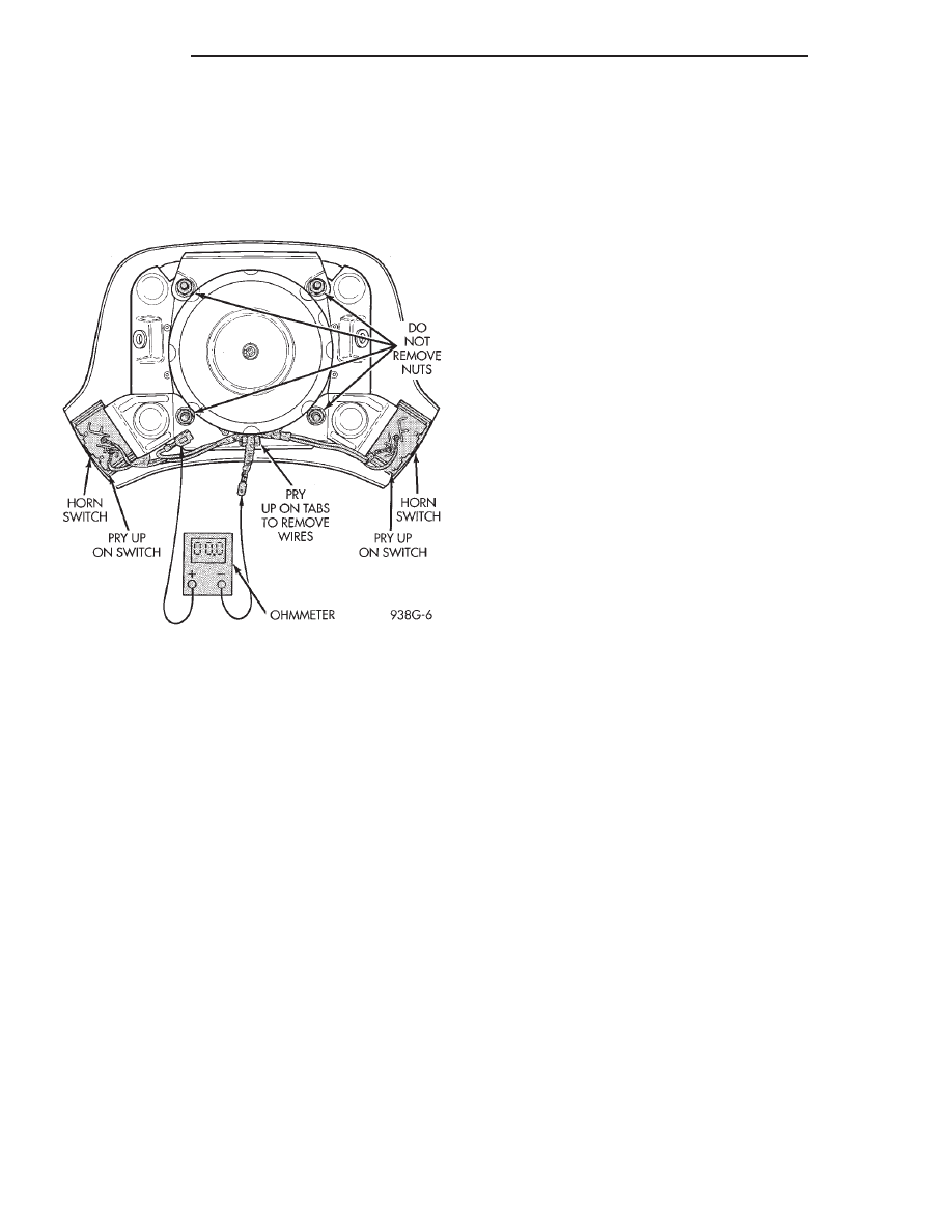
HORN SWITCH

(1) Using ohmmeter, connect one lead to ground

wire and the other lead to the positive wire (Fig. 3).

(2) Depress horn switch, should have continuity

repeat for other switch. If no continuity replace
switches.

HORN RELAY

(1) Remove horn relay.
(2) Using ohmmeter, test for continuity between

ground and terminal 12 of junction block.

(a) When the horn switch is not depressed, no

continuity.

(b) Continuity to ground when horn switch is

depressed.

(c) If continuity is not correct repair horn switch

or wiring as necessary. Refer to Group 8W, Wiring
diagrams.
(3) Using voltmeter, test voltage at:

(a) Terminal 11 and 13 test for battery voltage

from fuse F30.

(b) If voltage is incorrect repair as necessary.

Refer to Group 8W, Wiring Diagrams.
(4) Insert a jumper wire between terminals 13 and

15 of the junction block.

(a) If horns sound replace relay.
(b) If the horns do not sound, install horn relay

and refer to Horn Diagnosis and Testing.

SYSTEM TEST

CAUTION: Continuous

sounding

of

horns

may

cause horn relay to fail.

Check fuse 18 in the Junction Block and fuse L in

the Power Distribution Center. Refer to Horn System
Test table.

Fig. 3 Horn Switch

8G - 2

HORNS

300M

DIAGNOSIS AND TESTING (Continued)

HORN SYSTEM TEST

CONDITION

POSSIBLE CAUSE

CORRECTION

HORN SOUNDS CONTINUOUSLY.
NOTE: IMMEDIATELY UNPLUG
HORN AND RELAY IN THE
JUNCTION BLOCK

1. FAULTY HORN RELAY.
2. HORN CONTROL CIRCUIT
TO RELAY SHORTED TO
GROUND.
3. HORN RELAY CONTROL
CIRCUIT X3 SHORTING TO
GROUND INSIDE STEERING
WHEEL.
4. PINCHED HORN SWITCH
WIRE UNDER DRIVER AIRBAG
MODULE.
5. DEFECTIVE HORN SWITCH

1. REFER TO HORN RELAY TEST.
2. CHECK HORN RELAY TERMINAL 7 IN
JUNCTION BLOCK FOR CONTINUITY
TO GROUND INDICATES:
A. WIRING HARNESS SHORTED TO
GROUND.
B. FIND THE SHORT AND REPAIR AS
NECESSARY.
3. REMOVE DRIVER AIRBAG MODULE
AND CHECK FOR RUBBING, SHORTED
OR LOOSE WIRE CONNECTOR AND
REPAIR AS NECESSARY.
4. REPLACE DRIVER AIRBAG MODULE.
5. REPLACE DRIVER AIRBAG MODULE.

HORN SOUND INTERMITTENTLY
AS THE STEERING WHEEL IS
TURNED.

1. HORN RELAY CONTROL
CIRCUIT 3 IS SHORTED TO
GROUND INSIDE STEERING
WHEEL.
2. PINCHED HORN SWITCH
WIRE UNDER DRIVER AIRBAG
MODULE
3. DEFECTIVE HORN SWITCH

1. REMOVE DRIVER AIRBAG MODULE
AND CHECK FOR RUBBING OR LOOSE
WIRE/CONNECTOR, REPAIR AS
NECESSARY.
2. REPLACE DRIVER AIRBAG MODULE.
3. REPLACE DRIVER AIRBAG MODULE.

HORN DOES NOT SOUND

1. CHECK FUSE 18 IN THE
JUNCTION BLOCK.
2. NO VOLTAGE AT HORN
RELAY TERMINALS 1 & 2 AND
FUSE IS OK.
3. OPEN CIRCUIT FROM
TERMINAL 7 OF THE RELAY
TO HORN SWITCH X3
CIRCUIT.
4. DEFECTIVE OR DAMAGED
HORN.
5. DEFECTIVE HORN SWITCH

1. REPLACE FUSE IF BLOWN AS
REPAIR AS NECESSARY.
2. NO VOLTAGE, REPLACE JUNCTION
BLOCK OR REPAIR AS NECESSARY.
3. REPAIR CIRCUIT AS NECESSARY.
4. VOLTAGE AT HORN WHEN HORN
SWITCH IS PRESSED, REPLACE
HORN.
5. REPLACE DRIVER AIRBAG MODULE.

FUSE BLOWS WHEN HORN IS
BLOWN

1. SHORT CIRCUIT IN HORN
OR HORN WIRING

1. REMOVE HORN RELAY, CHECK FOR
SHORTED HORN OR HORN WIRING.
DISCONNECT HORN WIRE HARNESS
TO ISOLATE SHORT AND REPAIR AS
NECESSARY.

FUSE BLOWS WITHOUT
BLOWING HORN

1. SHORT CIRCUIT

1. REMOVE RELAY, INSTALL NEW
FUSE, IF FUSE DOES NOT BLOW
REPLACE HORN RELAY. IF FUSE
BLOWS WITH RELAY REMOVED,
CHECK FOR SHORT TO GROUND WITH
OHMMETER BETWEEN TERMINALS 1 &
2 AND THE FUSE TERMINAL. REPAIR
AS NECESSARY.

NOTE: FOR WIRING REPAIRS
REFER TO GROUP 8W, WIRE
DIAGRAMS.

300M

HORNS

8G - 3

DIAGNOSIS AND TESTING (Continued)

REMOVAL AND INSTALLATION

HORN

REMOVAL

(1) Open hood and disconnect the negative battery

cable remote terminal from the remote battery post
(Fig. 4).

(2) Disconnect wire connector.
(3) Remove the horn bracket mounting bolt and

remove horn.

NOTE: Do not disconnect horn from horn bracket.

INSTALLATION

For installation, reverse the above procedures.

HORN SWITCHES

WARNING:

BEFORE BEGINNING ANY AIRBAG

SYSTEM REMOVAL OR INSTALLATION PROCE-
DURES, REMOVE AND ISOLATE THE BATTERY
NEGATIVE CABLE FROM THE VEHICLE BATTERY.
THIS IS THE ONLY SURE WAY TO DISABLE THE
AIRBAG SYSTEM. FAILURE TO DO THIS COULD
RESULT IN ACCIDENTAL AIRBAG DEPLOYMENT
AND POSSIBLE PERSONAL INJURY.

REMOVAL

(1) Open hood and disconnect the negative battery

cable remote terminal from the remote battery post
(Fig. 4).

(2) Remove the two speed control switches or cover

plates from the steering wheel.

(3) Remove the screws that attach the driver air-

bag module to the steering wheel.

(4) Lift the module to gain access and disconnect

the squib and horn wire.

(5) Place airbag module on a clean level surface

with pad facing upward.

(6) Push switch locking tab inward and remove

switch from module. Repeat for other switch.

(7) Disconnect the ground wire from the retainer

plate on the back side of the module. Bend the two
retainer tabs on the bracket to release the horn
switch wires.

INSTALLATION

For installation, reverse the above procedures.

Assure that the switch is locked into position. Use
caution not to pinch wires.

HORN RELAY

REMOVAL

(1) Using ohmmeter, connect one lead to ground

wire and the other lead to the positive wire (Fig. 3).

(2) Open the driver’s door and remove the right

instrument panel end cover.

(3) Remove the horn relay (Fig. 5).

INSTALLATION

For installation, reverse the above procedures.

Fig. 4 Negative Battery Cable Remote Terminal

Fig. 5 Horn Relay Location

8G - 4

HORNS

300M

VEHICLE SPEED CONTROL SYSTEM

CONTENTS

page

page

GENERAL INFORMATION

INTRODUCTION . . . . . . . . . . . . . . . . . . . . . . . . . 1

DESCRIPTION AND OPERATION

POWERTRAIN CONTROL MODULE . . . . . . . . . . 2
SERVO CABLE . . . . . . . . . . . . . . . . . . . . . . . . . . 2
SPEED CONTROL SERVO . . . . . . . . . . . . . . . . . . 1
SPEED CONTROL SWITCHES . . . . . . . . . . . . . . 1
STOP LAMP SWITCH . . . . . . . . . . . . . . . . . . . . . 2
VACUUM RESERVOIR . . . . . . . . . . . . . . . . . . . . 2

DIAGNOSIS AND TESTING

CHECKING FOR DIAGNOSTIC CODES . . . . . . . . 3
OVERSHOOT/UNDERSHOOT FOLLOWING

SPEED CONTROL SET . . . . . . . . . . . . . . . . . . . 3

ROAD TEST . . . . . . . . . . . . . . . . . . . . . . . . . . . . 2

SERVO VACUUM TEST . . . . . . . . . . . . . . . . . . . . 6
SPEED CONTROL ELECTRICAL TEST . . . . . . . . 3
STOP LAMP SWITCH TEST . . . . . . . . . . . . . . . . 6
VACUUM SUPPLY TEST . . . . . . . . . . . . . . . . . . . 6

REMOVAL AND INSTALLATION

POWERTRAIN CONTROL MODULE . . . . . . . . . . 8
SERVO . . . . . . . . . . . . . . . . . . . . . . . . . . . . . . . . 7
SPEED CONTROL SERVO CABLE—2.7L . . . . . . 7
SPEED CONTROL SERVO CABLE—3.2/3.5L . . . 8
SPEED CONTROL SWITCH . . . . . . . . . . . . . . . . . 7
STOP LAMP SWITCH . . . . . . . . . . . . . . . . . . . . 7
VACUUM RESERVOIR . . . . . . . . . . . . . . . . . . . . 8

SPECIFICATIONS

TORQUE . . . . . . . . . . . . . . . . . . . . . . . . . . . . . . . 8

GENERAL INFORMATION

INTRODUCTION

The speed control system is electronically con-

trolled and vacuum operated. The electronic control
is integrated into the powertrain control module,
located on the driver’s side under the speed control
servo. The controls are located on the steering wheel.
The ON, OFF, and SET buttons are located on the
left side of the airbag module. The RESUME,
ACCEL, CANCEL and COAST buttons are located on
the right side of the airbag module (Fig. 1).

The system is designed to operate at speeds above

30 mph (48 km/h).

WARNING:

THE USE OF SPEED CONTROL IS

NOT RECOMMENDED WHEN DRIVING CONDITIONS
DO

NOT

PERMIT

MAINTAINING

A

CONSTANT

SPEED, SUCH AS IN HEAVY TRAFFIC OR ON
ROADS THAT ARE WINDING, ICY, SNOW COVERED,
OR SLIPPERY.

DESCRIPTION AND OPERATION

SPEED CONTROL SERVO

The servo unit consists of a solenoid valve body,

and a vacuum chamber. The PCM controls the sole-
noid valve body. The solenoid valve body controls the
application and release of vacuum to the diaphragm

of the vacuum servo. The servo unit cannot be
repaired and is serviced only as a complete assembly.

SPEED CONTROL SWITCHES

There are two separate switch pods that operate

the

speed

control

system.

The

steering-wheel-

mounted switches use multiplexed circuits to provide
inputs to the PCM for ON, OFF, RESUME, ACCEL-
ERATE, SET, DECEL and CANCEL modes. Refer to
the owner’s manual for more information on speed
control switch functions and setting procedures.

Fig. 1 Speed Control Switches

300M

VEHICLE SPEED CONTROL SYSTEM

8H - 1


Content   ..  73  74  75  76   ..