Chrysler Crossfire. Manual - part 859


  Index      Chrysler     Chrysler Crossfire - service repair manual 2005 year


Search            


Content   ..  857  858  859  860   ..


Chrysler Crossfire. Manual - part 859


9711 RIGHT ROTATION RELAY CONTROL CIRCUIT OPEN/SHORT TO B(+) (CONTINUED)
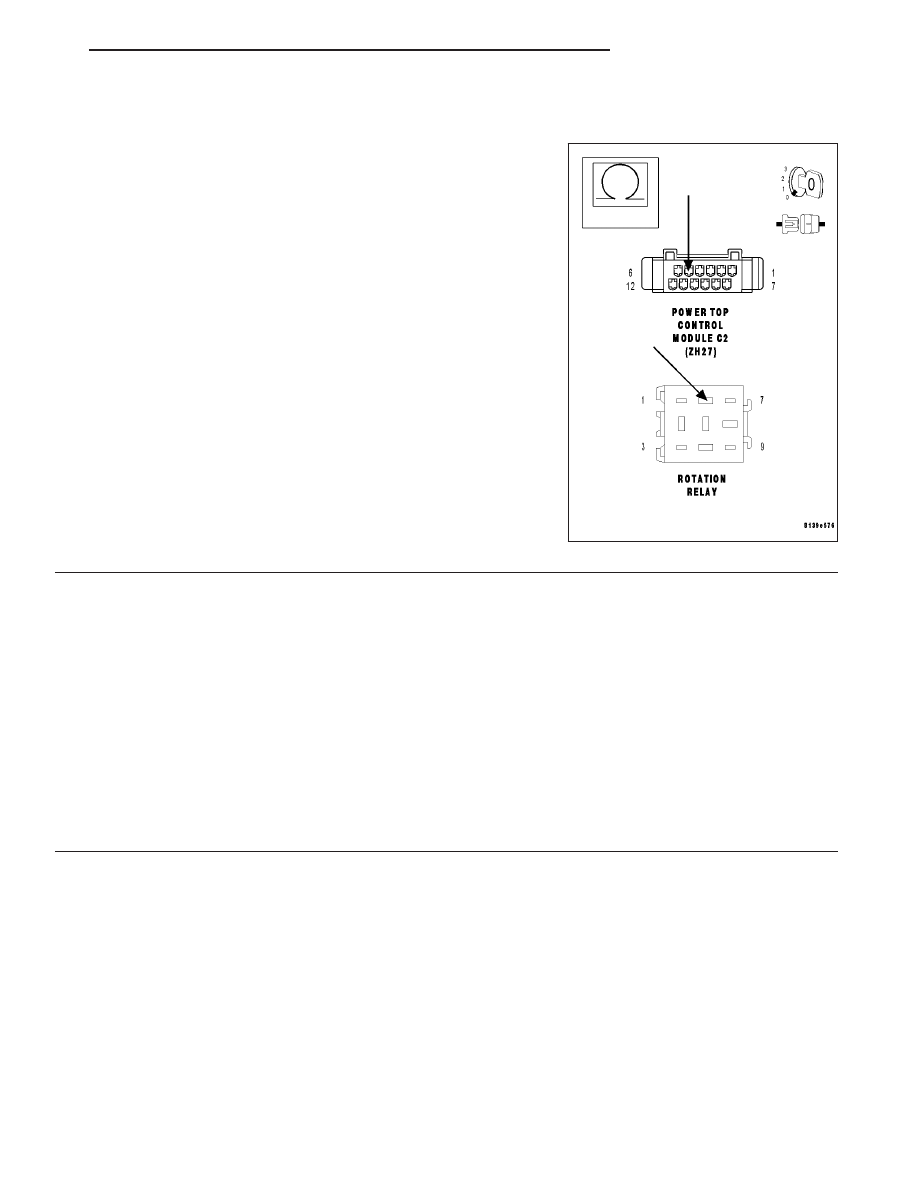
5.

Open Rotation Relay Ground circuit

With the ignition off.

Measure the resistance of the Rotation Relay Ground circuit from the
Right Rotation Relay harness connector to the PTCM C2 harness con-
nector.

Is the resistance below 5.0 ohms?

Yes

>> Replace the Right Rotation Relay.

Perform POWER TOP CONTROL MODULE VERIFICA-
TION TEST.

No

>> Repair the Rotation Relay Ground circuit for an open.

Perform POWER TOP CONTROL MODULE VERIFICA-
TION TEST.

6.

Rotation Relay Ground Circuit

Turn the ignition off.

Disconnect the Power Top Control Module C2 harness connector.

Measure the resistance between the Rotation Relay Ground circuit and the Right Rotation Relay Control circuit at
the Power Top Control Module C2 harness connector.

Is the resistance between 60.0 - 90.0 ohms?

Yes

>> Replace the Power Top Control Module.(Refer to 8 - ELECTRICAL/ELECTRONIC CONTROL MOD-

ULES/POWER TOP CONTROL MODULE - REMOVAL).

Perform POWER TOP CONTROL MODULE VERIFICATION TEST.

No

>> Repair the Rotation Relay Ground circuit for an open.

Perform POWER TOP CONTROL MODULE VERIFICATION TEST.

ZH

CONVERTIBLE TOP

23 - 107

9710 LEFT ROTATION RELAY CONTROL CIRCUIT SHORT TO GROUND

23 - 108

CONVERTIBLE TOP

ZH

9710 LEFT ROTATION RELAY CONTROL CIRCUIT SHORT TO GROUND (CONTINUED)

When Monitored: With the ignition on, the Power Top Control Module continuously senses the voltage
on the Left Rotation Relay Control circuit.

Set Condition: When the Power Top Control Module senses high current flow on the Left Rotation
Relay Control circuit when the Power Top Switch is pressed in the direction to lower the top.

Possible Causes

LEFT ROTATION RELAY

LEFT ROTATION RELAY CONTROL CIRCUIT SHORTED TO GROUND

POWER TOP CONTROL MODULE

Always perform the Pre-Diagnostic Troubleshooting procedure before proceeding.

Diagnostic Test

1.

Left Rotation Relay Control Circuit For Short To Ground

Turn the ignition off.

Disconnect the Power Top Control Module C2 harness connector.

Note: Check connectors — Clean/repair as necessary.
Measure the resistance between ground and the Left Rotation Relay
Control circuit.

Is the resistance above 100k ohms?

Yes

>> Replace the Power Top Control Module.(Refer to 8 -

ELECTRICAL/ELECTRONIC

CONTROL

MODULES/

POWER TOP CONTROL MODULE - REMOVAL).

Perform POWER TOP CONTROL MODULE VERIFICA-
TION TEST.

No

>> Go To 2

2.

Left Rotation Relay

With the ignition off.

Disconnect the Left Rotation Relay harness connector.

Note: Check connectors — Clean/repair as necessary.
Measure the resistance between ground and the Left Rotation Relay
Control circuit.

Is the resistance above 100k ohms?

Yes

>> Replace the Left Rotation Relay.

Perform POWER TOP CONTROL MODULE VERIFICA-
TION TEST.

No

>> Repair the Left Rotation Relay Control circuit for a short to

ground.

Perform POWER TOP CONTROL MODULE VERIFICA-
TION TEST.

ZH

CONVERTIBLE TOP

23 - 109

9721 LEFT ROTATION RELAY CONTROL CIRCUIT OPEN/SHORT TO B(+)

23 - 110

CONVERTIBLE TOP

ZH


Content   ..  857  858  859  860   ..