Chrysler Crossfire. Manual - part 762
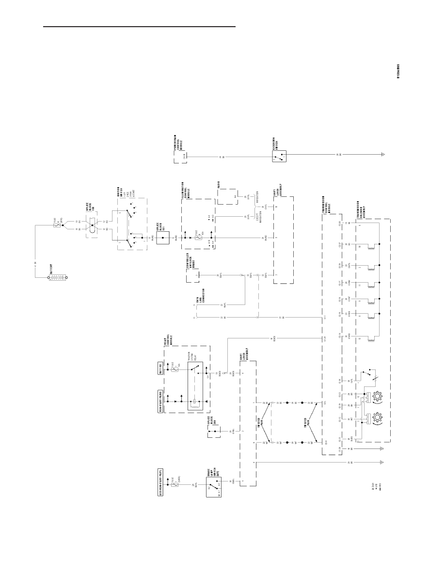
SCHEMATICS AND DIAGRAMS
AUT
OMA
TIC
TRANSMISSION
CIRCUIT
DIAGRAM
ZH
NAG1 - ELECTRICAL DIAGNOSTICS
21 - 197
|
|
|
SCHEMATICS AND DIAGRAMS AUT OMA TIC TRANSMISSION CIRCUIT DIAGRAM ZH NAG1 - ELECTRICAL DIAGNOSTICS 21 - 197 |