Chrysler Crossfire. Manual - part 597
(P0521) ENGINE OIL SENSOR QUALITY PERFORMANCE (CONTINUED)
When Monitored and Set Condition
•
When Monitored: With the engine running.
•
Set Condition: Anytime the Powertrain Control Module (PCM) senses the Oil Quality value is above 4.0.
•
Note: The engine oil must be changed before this test can be accurately conducted.
POSSIBLE CAUSES
WATER IN THE OIL
CONTAMINATED OIL
OIL SENSOR SIGNAL CIRCUIT OPEN
OIL SENSOR SIGNAL CIRCUIT SHORT TO GROUND
OIL SENSOR SIGNAL CIRCUIT SHORT TO VOLTAGE
5-VOLT SUPPLY CIRCUIT OPEN
5-VOLT SUPPLY CIRCUIT SHORT TO GROUND
5-VOLT SUPPLY CIRCUIT SHORT TO VOLTAGE
5-VOLT SUPPLY CIRCUIT SHORT TO SENSOR GROUND CIRCUIT
OIL SENSOR SIGNAL CIRCUIT SHORT TO SENSOR GROUND CIRCUIT
OIL SENSOR SIGNAL CIRCUIT SHORT TO 5-VOLT SUPPLY CIRCUIT
SENSOR GROUND CIRCUIT OPEN
MANIFOLD ABSOLUTE PRESSURE SENSOR
ENGINE OIL SENSOR
POWERTRAIN CONTROL MODULE
For a complete Powertrain Control Module Circuit Diagram, (Refer to 9 - ENGINE - SCHEMATICS AND DIA-
GRAMS).
Diagnostic Test
1.
PRE-DIAGNOSTIC CHECK OUT
Note: Always perform diagnostics with a fully charged battery.
Note: Check connectors — Clean/repair as necessary. Poor pin to
terminal connections can set DTCs.
Note: Check for applicable TSBs related to the problem.
Turn the ignition on.
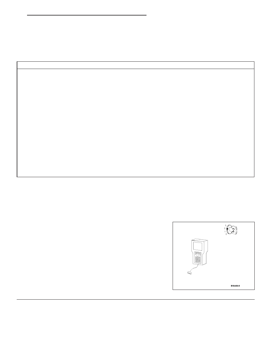
With the DRB III
T
, read PCM DTCs.
Using the wiring diagram/schematic as a guide, inspect the wiring and
connectors. Repair as necessary.
Perform this procedure prior to symptom diagnosis.
Continue
Go To 2
ZH
ENGINE - ELECTRICAL DIAGNOSTICS
9 - 533