Chrysler Crossfire. Manual - part 571


  Index      Chrysler     Chrysler Crossfire - service repair manual 2005 year


Search            


Content   ..  569  570  571  572   ..


Chrysler Crossfire. Manual - part 571


(P0410) SECONDARY AIR INJECTION SYSTEM (CONTINUED)

11.

AIR PUMP FUSE OPEN

Turn the ignition off.

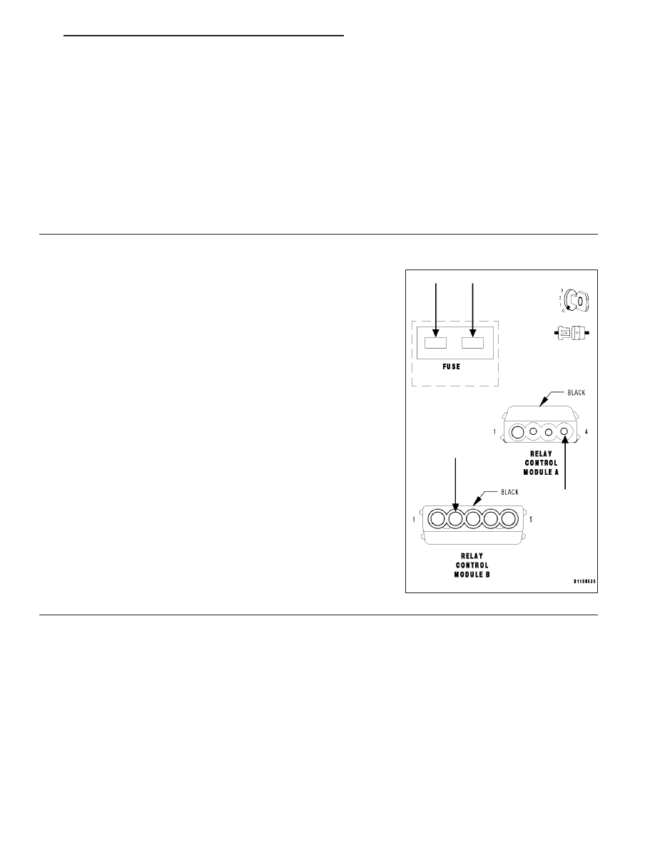
Inspect the 40 amp Air Pump Fuse for an open or high resistance connection.

Is the 40 amp Air Pump Fuse good?

Yes

>> Go To 12

No

>> Check the Air Pump Relay Output circuit, Relay Control Module, and Air Pump Relay for a short to

ground. Repair as necessary. If OK, replace the Air Pump and Air Pump Fuse. (Refer to 25 - EMIS-
SIONS CONTROL/AIR INJECTION/PUMP - REMOVAL).

Perform POWERTRAIN VERIFICATION TEST - VER 2.

12.

CHECK THE AIR PUMP RELAY

With the ignition off.

Reconnect the Air Pump harness connector.

Disconnect the Relay Control Module A and B harness connectors.

Note: Check connectors — Clean/repair as necessary.
Connect a fused jumper wire between pin 2 of the Relay Control Mod-
ule B harness connector and pin 4 of the Relay control Module A har-
ness connector.

Turn the ignition on.

Does the Air Pump run?

Yes

>> Replace the Relay Control Module.

Perform POWERTRAIN VERIFICATION TEST - VER 2.

No

>> Repair the Air Pump Relay Output circuit for an open.

Perform POWERTRAIN VERIFICATION TEST - VER 2.

ZH

ENGINE - ELECTRICAL DIAGNOSTICS

9 - 429

(P0410) SECONDARY AIR INJECTION SYSTEM (CONTINUED)

13.

INTERMITTENT WIRING AND CONNECTORS

The condition that caused this DTC to set is currently not present. Inspect the related wiring harness for a possible
intermittent condition.

Note: Check connectors — Clean/repair as necessary. Poor pin to terminal connections can set DTCs.

Note: Check for any Technical Service Bulletins that may apply.
Using the wiring diagram/schematic as a guide, inspect the wiring and connectors specific to this DTC. Wiggle the
wires while checking for shorts and open circuits.

Were there any problems found?

Yes

>> Repair as necessary.

Perform POWERTRAIN VERIFICATION TEST - VER 2.

No

>> The condition that caused this DTC to set is currently not present. Inspect the related wiring harness for

a possible intermittent condition.

9 - 430

ENGINE - ELECTRICAL DIAGNOSTICS

ZH

(P0412) SECONDARY AIR INJECTION SWITCHOVER SOLENOID CIRCUIT

ZH

ENGINE - ELECTRICAL DIAGNOSTICS

9 - 431

(P0412) SECONDARY AIR INJECTION SWITCHOVER SOLENOID CIRCUIT (CONTINUED)

When Monitored and Set Condition

When Monitored: Continuously with the ignition on.

Set Condition: An improper voltage level has been detected by the Powertrain Control Module (PCM) on the
air pump solenoid control circuit.

POSSIBLE CAUSES

FUSED ENGINE CONTROL RELAY OUTPUT CIRCUIT OPEN

AIR PUMP SWITCHOVER SOLENOID CONTROL CIRCUIT OPEN

AIR PUMP SWITCHOVER SOLENOID CONTROL CIRCUIT SHORT TO GROUND

AIR PUMP SWITCHOVER SOLENOID

POWERTRAIN CONTROL MODULE

For a complete Powertrain Control Module Circuit Diagram, (Refer to 9 - ENGINE - SCHEMATICS AND DIA-
GRAMS).

Diagnostic Test

1.

PRE-DIAGNOSTIC CHECK OUT

Note: Always perform diagnostics with a fully charged battery.

Note: Check connectors — Clean/repair as necessary. Poor pin to
terminal connections can set DTCs.

Note: Check for applicable TSBs related to the problem.
Turn the ignition on.

With the DRB III

T

, read PCM DTCs.

Using the wiring diagram/schematic as a guide, inspect the wiring and
connectors. Repair as necessary.

Perform this procedure prior to symptom diagnosis.

Continue

Go To 2

2.

ACTUATE THE SECONDARY AIR PUMP SWITCHOVER SOLENOID

Turn the ignition on.

With the DRB III

T

, actuate the AIRPUMP SWITCHOVER.

Touch the Air Pump Switchover Solenoid with your hand.

Does the Switchover Solenoid click on and off?

Yes

>> Go To 7

No

>> Go To 3

9 - 432

ENGINE - ELECTRICAL DIAGNOSTICS

ZH


Content   ..  569  570  571  572   ..