Chrysler Crossfire. Manual - part 560


  Index      Chrysler     Chrysler Crossfire - service repair manual 2005 year


Search            


Content   ..  558  559  560  561   ..


Chrysler Crossfire. Manual - part 560


(P0325) KNOCK SENSOR 1 CIRCUIT LOW (CONTINUED)

4.

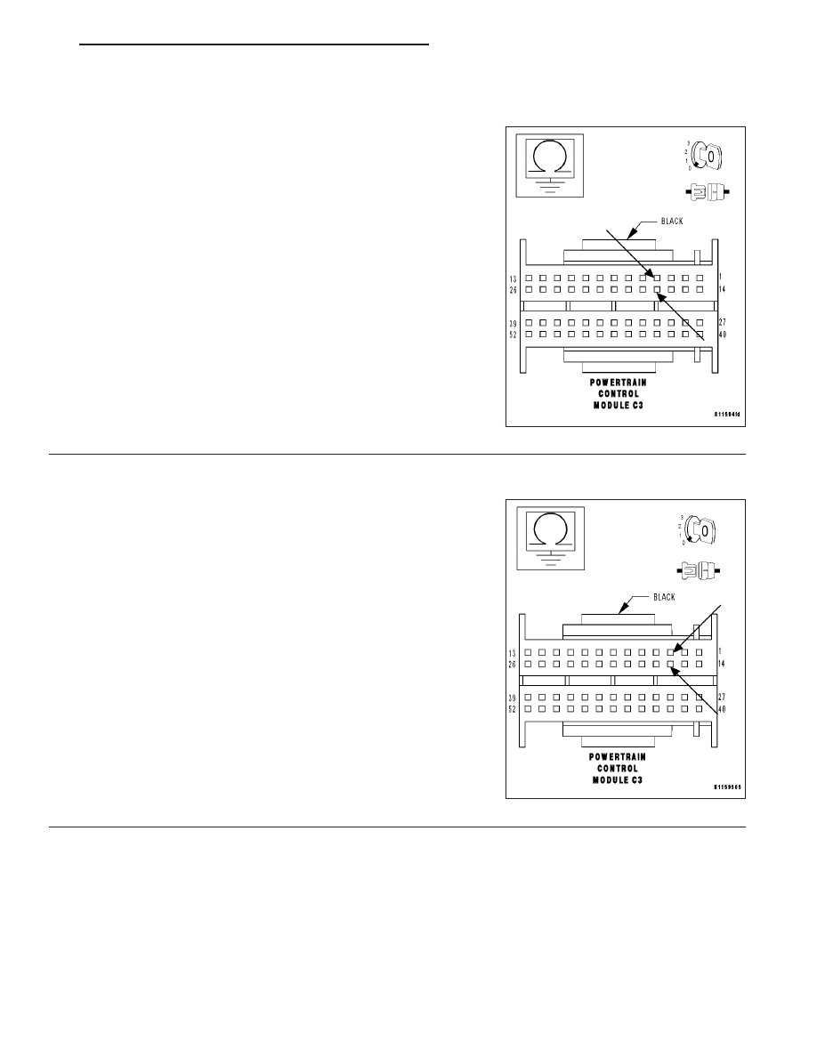
KNOCK SENSOR SIGNAL CIRCUIT SHORT TO GROUND

With the ignition off.

Measure the resistance between ground and the Knock Sensor Signal
circuit.

Is resistance above 100 kohms?

Yes

>> Go To 5

No

>> Repair the Knock Sensor Signal circuit for a short to

ground.

Perform POWERTRAIN VERIFICATION TEST - VER 2.

5.

SENSOR GROUND CIRCUIT SHORT TO GROUND

With the ignition off.

Measure the resistance between ground and the Sensor Ground cir-
cuit.

Is resistance above 100 kohms?

Yes

>> Go To 6

No

>> Repair the Sensor Ground circuit for a short to ground.

Perform POWERTRAIN VERIFICATION TEST - VER 2.

ZH

ENGINE - ELECTRICAL DIAGNOSTICS

9 - 385

(P0325) KNOCK SENSOR 1 CIRCUIT LOW (CONTINUED)

6.

SENSOR GROUND CIRCUIT SHORT TO VOLTAGE

Turn the ignition on.

Measure the voltage of the Sensor Ground circuit at the PCM C3 har-
ness connector.

Is the voltage below 1.0 volt?

Yes

>> Go To 7

No

>> Repair the Sensor Ground circuit for a short to voltage.

Perform POWERTRAIN VERIFICATION TEST - VER 2.

7.

KNOCK SENSOR SIGNAL CIRCUIT SHORT TO VOLTAGE

With the ignition on.

Measure the voltage of the Knock Sensor Signal circuit at the PCM C3
harness connector.

Is the voltage below 1.0 volt?

Yes

>> Go To 8

No

>> Repair the Knock Sensor Signal circuit for a short to volt-

age.

Perform POWERTRAIN VERIFICATION TEST - VER 2.

9 - 386

ENGINE - ELECTRICAL DIAGNOSTICS

ZH

(P0325) KNOCK SENSOR 1 CIRCUIT LOW (CONTINUED)

8.

KNOCK SENSOR SIGNAL CIRCUIT OPEN

Turn the ignition off.

Disconnect the Knock Sensor harness connector.

Note: Check connectors — Clean/repair as necessary.
Measure the resistance of the Knock Sensor Signal circuit from the
Knock Sensor harness connector to the PCM C3 harness connector.

Is the resistance below 5.0 ohms?

Yes

>> Go To 9

No

>> Repair the Knock Sensor Signal circuit for an open.

Perform POWERTRAIN VERIFICATION TEST - VER 2.

9.

SENSOR GROUND CIRCUIT OPEN

With the ignition off.

Measure the resistance of the Sensor Ground circuit from the Knock
Sensor harness connector to the PCM C3 harness connector.

Is the resistance below 5.0 ohms?

Yes

>> Go To 10

No

>> Repair the Sensor Ground circuit for an open.

Perform POWERTRAIN VERIFICATION TEST - VER 2.

ZH

ENGINE - ELECTRICAL DIAGNOSTICS

9 - 387

(P0325) KNOCK SENSOR 1 CIRCUIT LOW (CONTINUED)

10.

KNOCK SENSOR SIGNAL CIRCUIT SHORT TO SENSOR GROUND CIRCUIT

With the ignition off.

Measure the resistance between the Knock Sensor Signal circuit and
the Sensor Ground circuit at the Knock Sensor harness connector.

Is resistance above 100 kohms?

Yes

>> Replace the Knock Sensor. (Refer to 8 - ELECTRICAL/IG-

NITION CONTROL/KNOCK SENSOR - REMOVAL).

Perform POWERTRAIN VERIFICATION TEST - VER 2.

No

>> Repair the Knock Sensor Signal circuit for a short to the

Sensor Ground circuit.

Perform POWERTRAIN VERIFICATION TEST - VER 2.

11.

INTERMITTENT WIRING AND CONNECTORS

The conditions necessary to set this DTC are not present at this time.

Note: Check connectors — Clean/repair as necessary. Poor pin to terminal connections can set DTCs. Using
the wiring diagram/schematic as a guide, inspect the wiring and connectors specific to this DTC. Wiggle the
wires while checking for shorts and open circuits.

Note: Check for any Technical Service Bulletins that may apply.

Were there any problems found?

Yes

>> Repair as necessary.

Perform POWERTRAIN VERIFICATION TEST - VER 2.

No

>> The condition that caused this DTC to set is currently not present. Inspect the related wiring harness for

a possible intermittent condition.

9 - 388

ENGINE - ELECTRICAL DIAGNOSTICS

ZH


Content   ..  558  559  560  561   ..