Index Chrysler Chrysler Crossfire - service repair manual 2005 year
Search
Content .. 531 532 533 534 ..
Chrysler Crossfire. Manual - part 533
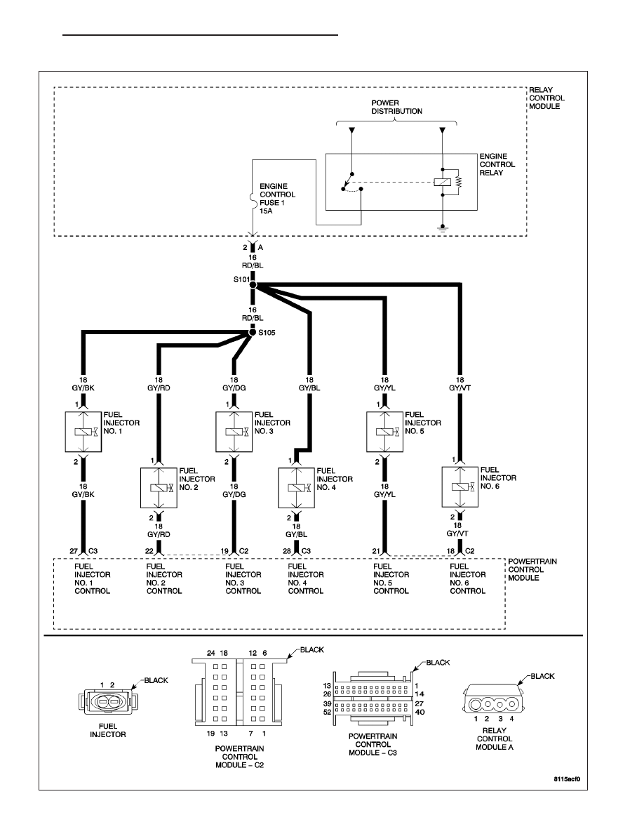
(P0200) FUEL INJECTOR CIRCUIT
ZH
ENGINE - ELECTRICAL DIAGNOSTICS
9 - 277