Chrysler Crossfire. Manual - part 522
(P0171) FUEL SYSTEM 1/1 RICH CONTROL OVER LIMIT (AT LOAD) (CONTINUED)
7.
ECT SENSOR OPERATION
Note: For this test to be valid, the thermostat must be operating
correctly.
Note: This test works best if performed on a cold engine (cold
soak).
Turn the ignition off until the engine is cold.
Turn the ignition on.
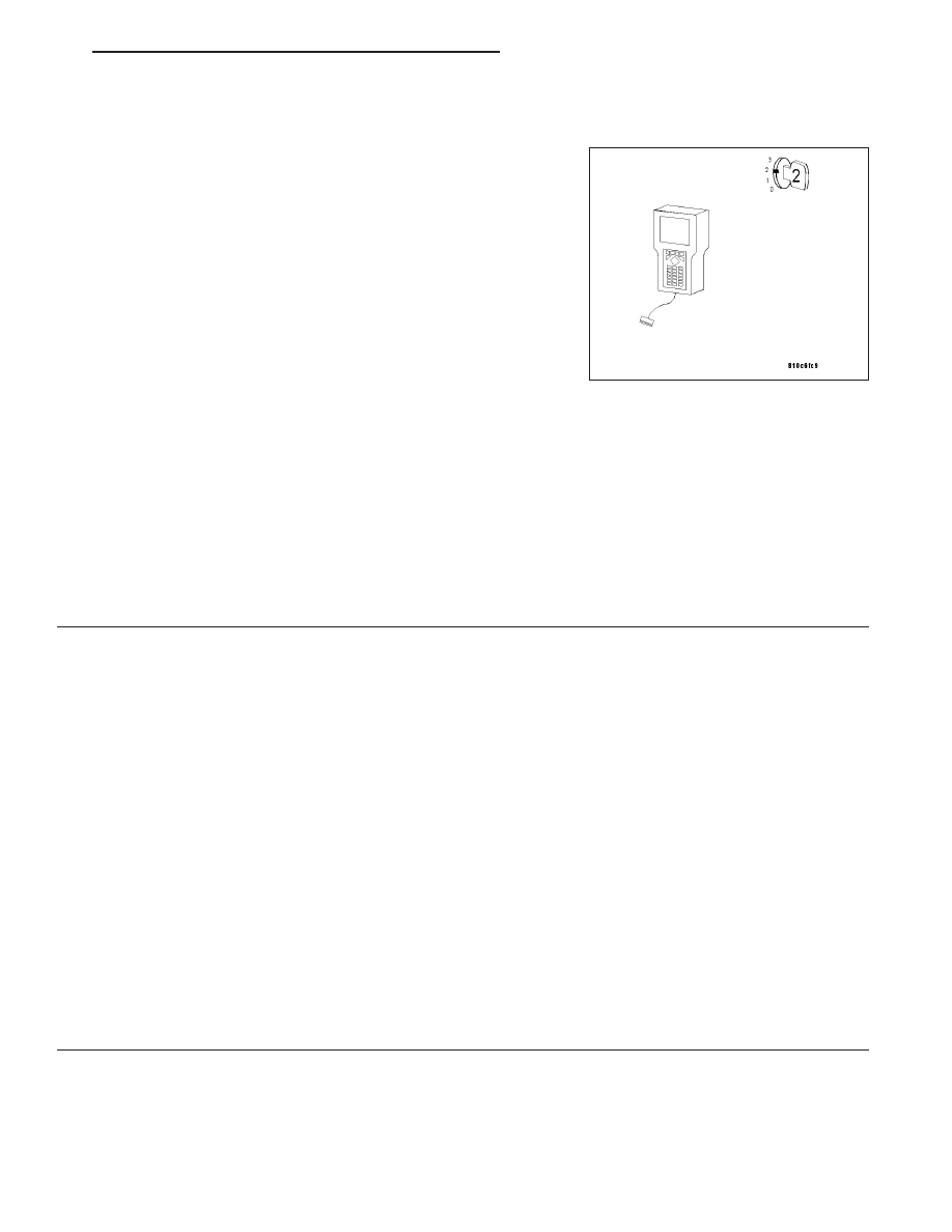
With the DRB III
T
, read the Engine Coolant Temperature Sensor
value. If the engine was allowed to sit overnight (cold soak), the tem-
perature value should be a sensible value that is somewhere close to
the ambient temperature.
Note: If engine coolant temperature is above 82°C (180°F), allow
the engine to cool until 65°C (150°F) is reached.
Start the Engine.
During engine warm-up, monitor the Engine Coolant Temperature value. The temperature value change should be a
smooth transition from start up to normal operating temperature 82°C (180°F). The value should reach at least 82°C
(180°F).
Did the Engine Coolant Temperature value increase with a smooth transition and did it reach at least 82°C
(180°F)?
Yes
>> Go To 8
No
>> Replace the Engine Coolant Temperature Sensor. (Refer to 7 - COOLING/ENGINE/ENGINE COOLANT
TEMP SENSOR - REMOVAL).
Perform POWERTRAIN VERIFICATION TEST - VER 2.
8.
ENGINE MECHANICAL PROBLEM
Turn the ignition off.
Check for any of the following conditions/mechanical problems.
AIR INDUCTION SYSTEM - must be free from restrictions.
ENGINE VACUUM - must be at least 440 mbar (13 in. Hg) in neutral.
ENGINE VALVE TIMING - must be within specifications.
ENGINE COMPRESSION - must be within specifications.
ENGINE EXHAUST SYSTEM - must be free of any restrictions or leaks.
TORQUE CONVERTER STALL SPEED - must be within specifications.
POWER BRAKE BOOSTER - must not have any internal vacuum leaks.
FUEL - must be free of contamination.
FUEL INJECTOR - must not be plugged or restricted; harness connectors must be connected to the correct injec-
tors.
Are there any engine mechanical problems?
Yes
>> Repair as necessary.
Perform POWERTRAIN VERIFICATION TEST - VER 2.
No
>> Go To 12
ZH
ENGINE - ELECTRICAL DIAGNOSTICS
9 - 233