Chrysler Crossfire. Manual - part 392


  Index      Chrysler     Chrysler Crossfire - service repair manual 2005 year


Search            


Content   ..  390  391  392  393   ..


Chrysler Crossfire. Manual - part 392


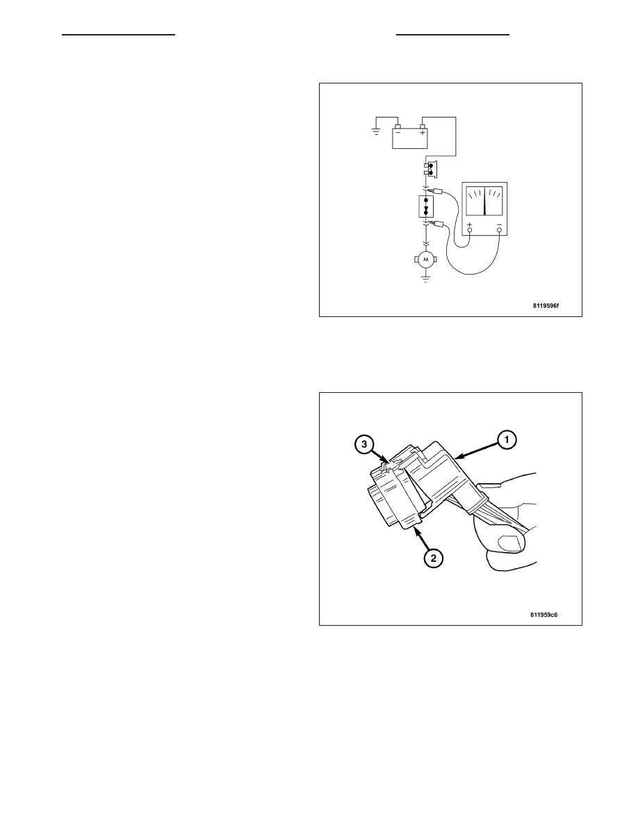
TESTING FOR A VOLTAGE DROP

1. Connect the positive lead of the voltmeter to the

side of the circuit closest to the battery.

2. Connect the other lead of the voltmeter to the other

side of the switch, component or circuit.

3. Operate the item.

4. The voltmeter will show the difference in voltage

between the two points.

CONNECTOR

REMOVAL

1. Disconnect battery.

2. Release Connector Lock(2).

3. Disconnect the connector(3) being repaired from its

mating half/component.

4. Remove the dress cover(1) (if applicable).

5. Release the Secondary Terminal Lock, if required.

6. Position the connector locking finger away from the

terminal using the proper special tool. Pull on the
wire to remove the terminal from the connector.

INSTALLATION

1. Insert the removed terminal in the same cavity on the repair connector.

2. Repeat steps for each terminal in the connector, being sure that all wires are inserted into the proper cavities.

For additional connector pin-out identification, refer to the wiring diagrams.

3. When the connector is re-assembled, the secondary terminal lock must be placed in the locked position to pre-

vent terminal push out.

4. Replace dress cover (if applicable).

5. Connect connector to its mating half/component.

6. Connect battery and test all affected systems.

ZH

8W-01 WIRING DIAGRAM INFORMATION

8W - 01 - 11

DIODE

REMOVAL

1. Disconnect the battery.

2. Locate the diode in the harness, and remove the

protective covering.

3. Remove the diode from the harness, pay attention

to the current flow direction(1).

INSTALLATION

1. Remove the insulation from the wires in the harness. Only remove enough insulation to solder in the new diode.

2. Install the new diode in the harness, making sure current flow is correct. If necessary, refer to the appropriate

wiring diagram for current flow.

3. Solder the connection together using rosin core type solder only. Do not use acid core solder.

4. Tape the diode to the harness using electrical tape. Make sure the diode is completely sealed from the elements.

5. Re-connect the battery and test affected systems.

TERMINAL

REMOVAL

1. Follow steps for removing terminals described in the connector removal section.

2. Cut the wire 6 inches from the back of the connector.

INSTALLATION

1. Select a wire from the terminal repair kit that best matches the color and gage of the wire being repaired.

2. Cut the repair wire to the proper length and remove one–half (1/2) inch of insulation.

3. Splice the repair wire to the wire harness (see wire splicing procedure). (Refer to 8 - ELECTRICAL/WIRING

DIAGRAM INFORMATION/WIRE - STANDARD PROCEDURE).

4. Insert the repaired wire into the connector.

5. Install the connector locking wedge, if required, and reconnect the connector to its mating half/component.

6. Re-tape the wire harness starting at 1–1/2 inches behind the connector and 2 inches past the repair.

7. Connect battery and test all affected systems.

8W - 01 - 12

8W-01 WIRING DIAGRAM INFORMATION

ZH

WIRE

STANDARD PROCEDURE

WIRE SPLICING

When splicing a wire, it is important that the correct gage be used as shown in the wiring diagrams.

1. Remove one-half (1/2) inch of insulation from each wire that needs to be spliced.

2. Place a piece of adhesive lined heat shrink tubing on one side of the wire. Make sure the tubing will be long

enough to cover and seal the entire repair area.

3. Place the strands of wire overlapping each other

inside of the splice clip(1).

4. Using crimping too(1)l, Mopar p/n 05019912AA,

crimp the splice clip and wires together.

ZH

8W-01 WIRING DIAGRAM INFORMATION

8W - 01 - 13

5. Solder the connection(2) together using a soldering

iron(3) and rosin core type solder(1) only.

CAUTION: DO NOT USE ACID CORE SOLDER.

6. Center the heat shrink tubing(2) over the joint and

heat using a heat gun. Heat the joint until the tub-
ing is tightly sealed and sealant(1) comes out of
both ends of the tubing.

8W - 01 - 14

8W-01 WIRING DIAGRAM INFORMATION

ZH


Content   ..  390  391  392  393   ..