Index Chrysler Chrysler Crossfire - service repair manual 2005 year
Search
Content .. 388 389 390 391 ..
Chrysler Crossfire. Manual - part 390
ZH
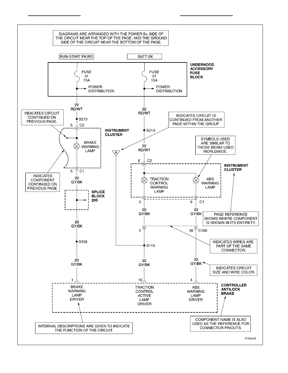
8W-01 WIRING DIAGRAM INFORMATION
8W - 01 - 3