Chrysler Crossfire. Manual - part 296
2. Using a hand held vacuum pump, connect an appropriate rubber hose 2 in. (50 mm) long to the disconnected
pneumatic supply line.
3. Apply 600 mbar (17.7 in. Hg) vacuum to the pneumatic supply line for 1 minute.
If after 1 minute the vacuum loss is less than 30 mbar (.9 in. Hg), the pneumatic supply lines and actuators are not
the cause of the fault. If after 1 minute the vacuum loss is greater than 30 mbar (.9 in. Hg), perform the Pneumatic
Actuator Test.
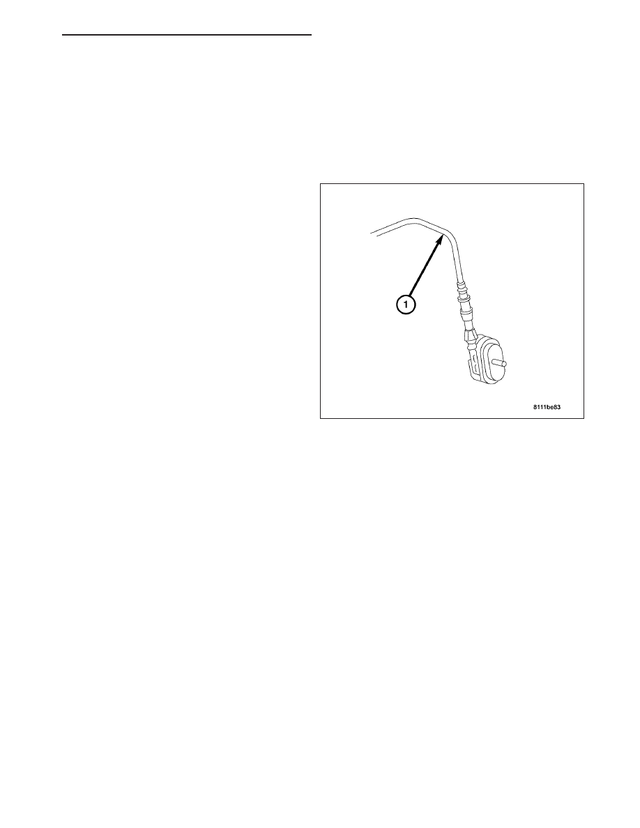
Pneumatic Actuator Test
1. Disconnect the pneumatic supply line (1) con-
nected to the pneumatic actuator.
2. Using a hand held vacuum pump, connect an
appropriate rubber hose 2 in. (50 mm) long to the
disconnected pneumatic actuator.
3. Apply 600 mbar (17.7 in. Hg) vacuum to the pneu-
matic actuator for 1 minute.
If after 1 minute the vacuum loss is less than 30 mbar
(.9 in. Hg), perform the Pneumatic Line Test. If after 1
minute the vacuum loss is greater than 30 mbar (.9 in.
Hg), replace the pneumatic actuator.
Pneumatic Line Test
1. Block off one end of the pneumatic supply line and connect a hand held vacuum pump to the other end of the
supply line.
2. Apply 300 mbar (8.9 in. Hg) vacuum to the pneumatic supply line for 1 minute.
If after 1 minute the vacuum loss is 0 mbar (0 in. Hg), then check for pressure and vacuum at the Central Locking
Pump/Security System Module. If after 1 minute the vacuum loss is greater than 0 mbar (0 in. Hg), replace the
pneumatic supply line.
STANDARD PROCEDURE - TOGGLING CUSTOMER PREFERENCES
Automatic Locking
The automatic locking function can be activated or deactivated with the DRB III
T
. The interior power door lock
switch may also be used with the ignition switched on by pressing and holding the power door lock switch for more
than 5 seconds in either the lock (auto locking switched on) or unlock (auto locking switched off) position. The inte-
rior power door lock switch can be inhibited with the DRB III
T
.
Global/Selective Central Locking
The keyless entry system has a Global or Selective mode function for central locking that can be programed by the
customer. The factory setting is Global, which will lock and unlock both doors, rear liftgate and fuel door centrally
when the respective button is pressed once. The Selective mode will only change which power locks unlock. To
activate the Selective mode, press both the Unlock and Lock buttons simultaneously for approximately five seconds
until the battery check lamp in the transmitter flashes twice. The Unlock button will then only unlock the driver door
and the fuel door when it is pressed once. Pressing the Unlock button a second time, unlocks the passenger’s door
and the rear liftgate. The factory setting can be restored by pressing both the Unlock and Lock buttons simulta-
neously again for approximately five seconds until the battery check lamp in the transmitter flashes twice. If the
vehicle was locked using the power lock switch in the center console while in the Selective mode, opening a door
ZH
POWER LOCKS - SERVICE INFORMATION
8N - 33