Chrysler Crossfire. Manual - part 194
SPECIFICATIONS
STARTER MOTOR
Starter Motor and Solenoid
Manufacturer
Engine Application
3.2L
Power Rating
Voltage
12 Volts
Number of Fields
Number of Poles
Number of Brushes
Drive Type
Free Running Test Voltage
Free Running Test Maximum Amperage Draw
Free Running Test Minimum Speed
Solenoid Closing Maximum Voltage Required
*Cranking Amperage Draw Test
*Test at operating temperature. Cold engine, tight (new) engine, or heavy oil will increase starter amperage draw.
TORQUE SPECIFICATIONS
DESCRIPTION
N·m
Ft. Lbs.
In. Lbs.
Starter Motor (B+) Terminal
14
10
—
Starter Motor Ground Terminal
6
—
52
Starter Motor Retaining Bolts
42
31
—
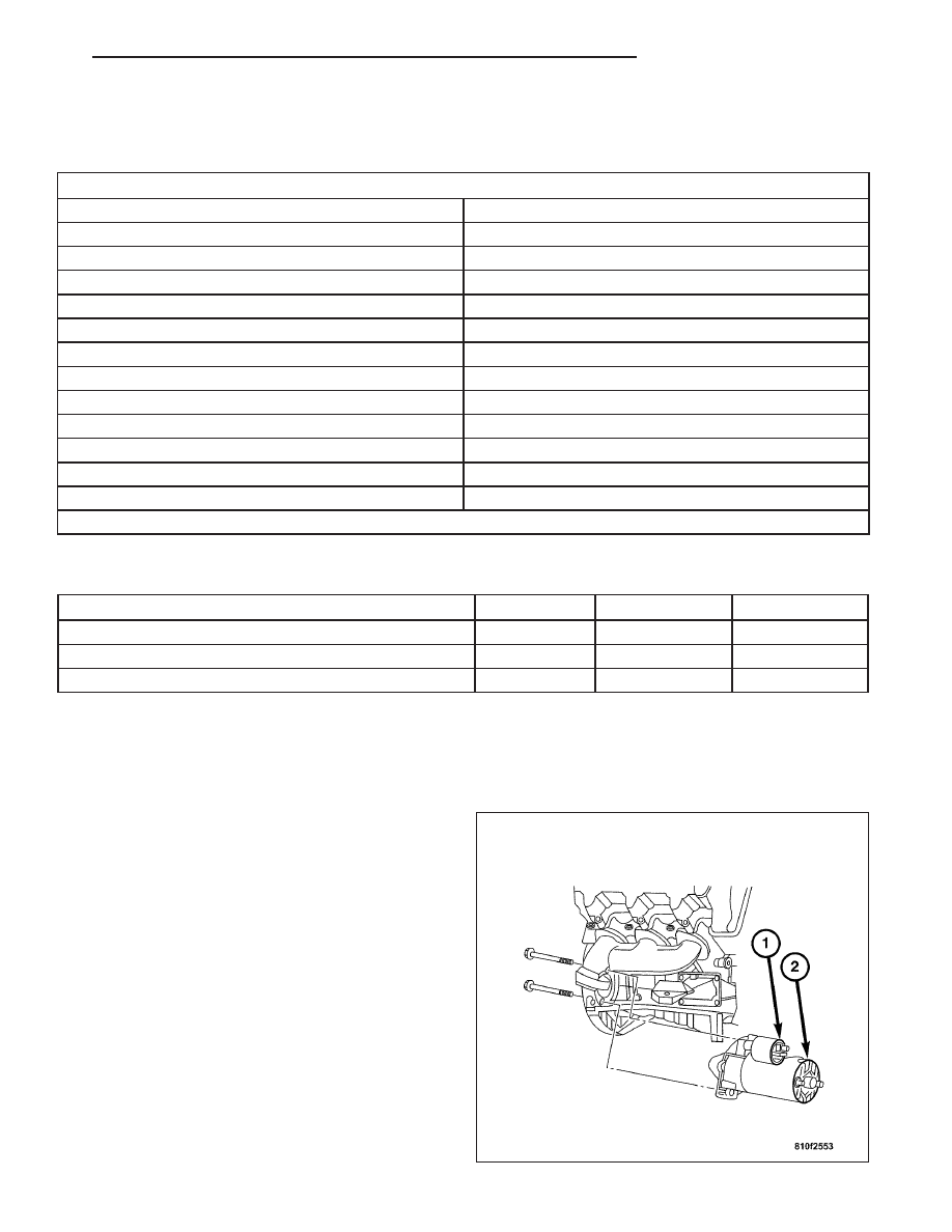
STARTER MOTOR
DESCRIPTION
The starter motor (2) is mounted with two bolts to the
transmission housing and is located on the right side
of the engine. The starter motor incorporates several
features to create a reliable, efficient, compact, light-
weight and powerful unit. The electric motor of the
starter features electromagnetic field coils wound
around pole shoes, and brushes contact the motor
commutator. The starter motor is serviced only as a
unit and cannot be repaired. The entire starter motor
(2) and starter solenoid unit (1) must be replaced if
either component is faulty or damaged.
ZH
STARTING SYSTEM
8F - 43