Content .. 1012 1013 1014 1015 ..
Chrysler Crossfire. Manual - part 1014
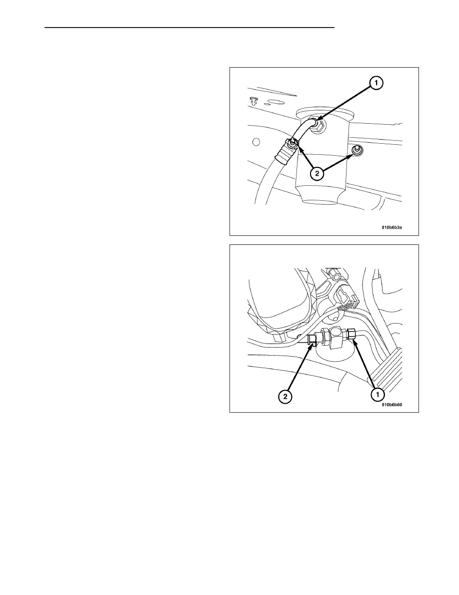
INSTALLATION
1. Install the receiver/drier to the vehicle.
2. Install the mounting nuts (2).
3. Install the lower pressure line (1). Tighten to 17
N·m (12 ft. lbs.).
4. Install left inner fender (front section).
5. Install the wheel and tire assembly.
6. Install the refrigerant pressure sensor (2).
7. Install the upper pressure line (1). Tighten to 17
N·m (12 ft. lbs.).
8. Connect the electrical connector (2).
9. Charge the refrigerant the system.
REFRIGERANT
DESCRIPTION
The refrigerant used in this Air Conditioning System is a HydroFluoroCarbon (HFC), type R-134a. Unlike R-12,
which is a ChloroFluoroCarbon (CFC), R-134a refrigerant does not contain ozone-depleting chlorine. R-134a refrig-
erant is a non-toxic, non-flammable, clear, and colorless liquefied gas.
Even though R-134a does not contain chlorine, it must be reclaimed and recycled just like CFC-type refrigerants.
This is because R-134a is a greenhouse gas and can contribute to global warming.
OPERATION
R-134a refrigerant is not compatible with R-12 refrigerant in an Air Conditioning System. Even a small amount of
R-12 added to an R-134a refrigerant system will cause Compressor failure, refrigerant oil sludge or poor Air Con-
ditioning System performance. In addition, the PolyAlkylene Glycol (PAG) synthetic refrigerant oils used in an
ZH
PLUMBING
24 - 159