Chrysler 300M, Dodge Interpid. Manual - part 22


  Index      Chrysler     Chrysler 300M / Concorde / Interpid / LHS, Dodge Interpid - service repair manual 2000-2004 year


Search            


Content   ..  20  21  22  23   ..


Chrysler 300M, Dodge Interpid. Manual - part 22


STANDARD PROCEDURE - WHEEL ALIGNMENT

PRE-WHEEL ALIGNMENT INSPECTION

Before any attempt is made to change or correct

the wheel alignment, the following inspection and
necessary corrections must be made to ensure proper
alignment.

(1) Verify that the fuel tank is full of fuel. If the

tank is not full, the reduction in weight will affect the
curb height of the vehicle and the alignment angles.

(2) The passenger and luggage compartments of

the vehicle should be free of any load that is not fac-
tory equipment.

(3) Check the tires on the vehicle. All tires must be

the same size and in good condition with approxi-
mately the same amount of tread wear. Inflate all
the tires to the recommended air pressure.

(4) Check the front wheel and tire assemblies for

excessive radial runout.

(5) Inspect lower ball joints and all steering link-

age for looseness, binding, wear or damage. Repair as
necessary.

(6) Check suspension fasteners for proper torque

and retighten as necessary.

(7) Inspect all suspension component rubber bush-

ings for signs of wear or deterioration. Replace any
faulty bushings or components before aligning the
vehicle.

(8) Check the vehicle’s curb height to verify it is

within specifications. Refer to Curb Height Measure-
ment.

WHEEL ALIGNMENT SETUP

(1) Position the vehicle on an alignment rack.
(2) Install all required alignment equipment on

the vehicle, per the alignment equipment manufac-
turer’s instructions. On this vehicle, a four-wheel
alignment is recommended.

NOTE: Prior to reading the vehicle’s alignment
readouts, the front and rear of vehicle should be
jounced. Induce jounce (rear first, then front) by
grasping the center of the bumper and jouncing
each end of vehicle an equal number of times. The
bumper should always be released when vehicle is
at the bottom of the jounce cycle.

(3) Read the vehicle’s current front and rear align-

ment settings. Compare the vehicle’s current align-
ment settings to the vehicle specifications for camber,
caster and toe-in. Refer to Specifications.

(4) If the rear alignment is out of specification,

adjust it first, before proceeding to the front. Rear
camber and caster are not adjustable. If rear camber
is out of specification, check for damaged or bent rear
suspension components.

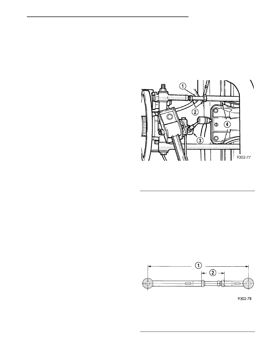
REAR WHEEL TOE ADJUSTMENT

(1) Loosen lateral link, adjustment link jam nuts

(Fig. 7). Rotate adjustment links as required to set
rear wheel Toe to specifications. Do not exceed the
maximum length dimensions of the lateral links
shown in (Fig. 8). Both dimensions must be
checked to ensure they do not exceed maxi-
mums allowed.

CAUTION: When setting rear toe-in on vehicle, the
maximum lengths of the adjustable lateral link at
the locations shown in (Fig. 8) must not be
exceeded. If these maximum lengths are exceeded,
inadequate retention of adjustment link to the inner
and outer link may result. Ensure that the adjust-
ment sleeve jam nuts are torqued to the required
specifications when the Toe setting procedure is
completed.

Fig. 7 Rear Wheel Toe Adjustment

1 - ADJUSTMENT LINK
2 - JAM NUTS
3 - SPINDLE
4 - LATERAL LINKS

Fig. 8 Lateral Link Maximum Length Dimensions

1 - 380mm
(MAX)
2 - 90mm
(MAX)

LH

WHEEL ALIGNMENT

2 - 57

WHEEL ALIGNMENT (Continued)

(2) Tighten lateral link, adjustment link lock-nuts

to 88 N·m (65 ft. lbs.) torque.

(3) Proceed to set the front wheel alignment. If

front camber and caster readings are within required
specifications, proceed to Front Wheel Toe Adjust-
ment. If not, refer to the following procedure to cor-
rect camber.

CAMBER AND CASTER

Front wheel Camber and Caster settings on this

vehicle are determined at the time the vehicle is
designed. This is done by determining the precise
mounting location of the vehicle’s suspension compo-
nents throughout the design and assembly processes
of the vehicle. This is called a Net-Build vehicle and
results in no normal requirement for adjustment of
the Camber and Caster after a vehicle is built, or
when servicing the suspension components. Thus,
Camber and Caster are not normally considered an
adjustable specification when performing an align-
ment on this vehicle. Though Camber and Caster are
not adjustable, they should be checked during the
alignment procedure to ensure they meet the manu-
facturers specifications.

If camber and caster do not meet required specifi-

cations, the vehicles suspension components should
be inspected for any signs of damage or bending.
This inspection must be done before perform-
ing the camber setting procedure.

If a vehicle has a drift or lead condition, the front

camber can be adjusted using the following camber
adjustment procedure. For diagnosis of a lead/pull
condition,

(Refer

to

2

-

SUSPENSION/WHEEL

ALIGNMENT - DIAGNOSIS AND TESTING).

CAUTION: Do not attempt to adjust the vehicles
Caster or Camber by heating, bending or modifying
the vehicle’s front suspension components.

FRONT CAMBER ADJUSTMENT

There are camber adjustment bolts and nuts avail-

able to allow front suspension camber adjustment in
the event the vehicle pulls even though the camber is
within specifications. This procedure involves replac-
ing the original strut clevis to knuckle attachment
bolts with special undersized bolts.

(1) Raise the front of vehicle by the frame until

the tires are not supporting the weight of the vehicle.

(2) Remove the tire and wheel assembly from the

location on the vehicle requiring camber adjustment.

CAUTION: When removing the strut to knuckle
bolts from the strut clevis bracket, do not allow
knuckle to pull away, putting a strain on the brake
flex hose.

CAUTION: The bolts attaching the strut to the steer-
ing knuckle are serrated in the area where they go
through the steering knuckle and strut. When
removing, do not turn the bolts in the steering
knuckle. If bolts are turned in the steering knuckle,
damage to the steering knuckle will result.

(3) Remove the nuts from the bolts attaching the

strut to the knuckle (Fig. 9). Tap the bolts out of the
knuckle.

(4) Loosely install the camber adjustment bolts

and nuts attaching the strut to the steering knuckle.
The bolts should be installed so the nuts are towards
the front of the vehicle.

(5) Install the tire and wheel assembly.
(6) If necessary, repeat steps 2 through 5 to the

other side of the vehicle.

(7) Lower the vehicle.
(8) Jounce the front and rear of vehicle.
(9) Adjust the front camber to the preferred set-

ting by pushing in or pulling outward on the top of
the wheel and tire as required. When camber is cor-
rect, tighten the upper and lower strut to knuckle
camber adjustment bolts to a torque of 203 N·m (150
ft. lbs.).

(10) Proceed to Front Wheel Toe Adjustment and

adjust front wheel toe as necessary.

FRONT WHEEL TOE ADJUSTMENT

(1) Center steering wheel and hold it in place

using a steering wheel clamp.

(2) Loosen the tie rod adjustment pinch bolt.

Rotate the adjustment sleeve to align toe to specifi-
cations (Fig. 10).

Fig. 9 Strut To Steering Knuckle Attaching Bolts

1 - STRUT ASSEMBLY
2 - NUTS
3 - STRUT ASSEMBLY TO STEERING KNUCKLE ATTACHING
BOLTS
4 - STEERING KNUCKLE

2 - 58

WHEEL ALIGNMENT

LH

WHEEL ALIGNMENT (Continued)

CAUTION: When setting toe on vehicle, the maxi-
mum dimension of exposed threads allowed on
inner and outer tie rod cannot exceed the distance
shown

(Fig.

11).

If

the

maximum

distance

is

exceeded, inadequate retention of either inner or
outer tie rod may result. Ensure that adjustment
pinch bolt is torqued to required specification when
Toe setting procedure is completed.

CAUTION: When torquing adjustment pinch bolt,
the following procedure must be followed to ensure
adequate retention of the adjustment sleeve. Not
following this procedure, could result in the Toe
Setting Adjustment changing and/or loosening of
the inner or outer tie rod ends.

NOTE: Use an appropriate tool on neck area of
outer tie rod to maintain the correct perpendicular
orientation of the tie rod end stud within the tie rod
end.

(3) After completion of toe adjustment procedure,

tighten tie rod pinch bolt (Fig. 11) to a torque of 38
N·m (28 ft. lbs.).

(1) Road test the vehicle after the initial wheel

alignment has been performed. If vehicle still drifts
or leads, repeat the front wheel alignment procedure
and adjust the camber to bias the cross camber set-
ting opposite of the direction in which the vehicle has
the tendency to lead. For example, if the vehicle
leads left, compensate by setting left front camber to
0.0° and right front camber up to +0.6°, allowing
both sides to remain within camber specifications.
The cross camber is still at 0.6° which is within the
allowed alignment specification.

STANDARD PROCEDURE - CURB HEIGHT
MEASUREMENT

The wheel alignment is to be checked and all align-

ment adjustments made with the vehicle at its
required curb height specification.

Vehicle height is to be checked with the vehicle on

a flat, level surface, preferably a vehicle alignment
rack. The tires are to be inflated to the recommended
pressure. All tires are to be the same size as stan-
dard equipment. Vehicle height is checked with the
fuel tank full of fuel, and no passenger or luggage
compartment load.

Vehicle height is not adjustable. If measurement is

not within specifications, inspect vehicle for bent or
weak suspension components. Compare parts tag on
suspect coil spring(s) to parts book and vehicle sales
code, checking for a match. Once removed from vehi-
cle, compare coil spring height to a correct new or
known good coil spring. The heights should vary if
the suspect spring is weak.

(1) Measure from the inboard edge of the wheel

opening fender lip directly above the wheel center
(spindle), to the floor or alignment rack surface.

(2) When measuring, maximum left-to-right differ-

ential is not to exceed 20 mm (0.79 in.).

(3) Compare measurements to specifications listed

in the following chart.

Fig. 10 Front Wheel Toe Adjustment Location

1 - ADJUSTMENT TOOL
2 - ADJUSTMENT PINCH BOLT
3 - TIE ROD END

Fig. 11 Tie Rod Thread Engagement Requirements

1 - OUTER TIE ROD
2 - ADJUSTER
3 - PINCH BOLT
4 - INNER TIE ROD
5 - ALLOWABLE THREADS EXPOSED ON OUTER TIE ROD AND
ADJUSTER IS A MAXIMUM OF 20 MILLIMETERS. REFER TO
AREA INDICATED ABOVE ON THE OUTER TIE ROD AND
ADJUSTER.

LH

WHEEL ALIGNMENT

2 - 59

WHEEL ALIGNMENT (Continued)

CURB HEIGHT SPECIFICATIONS

VEHICLE

FRONT

REAR

CONCORDE/300M

739 mm ± 20 mm

754 mm ± 20 mm

29.09 in. ± 0.79 in.

29.68 in. ± 0.79 in.

INTREPID

729 mm ± 20 mm

735 mm ± 20 mm

28.70 in. ± 0.79 in.

28.93 in. ± 0.79 in.

SPECIFICATIONS

WHEEL ALIGNMENT

NOTE: All specifications are given in degrees.

NOTE: All wheel alignments are to be set with the
vehicle at curb height. Refer to CURB HEIGHT MEA-
SUREMENT.

FRONT WHEEL ALIGNMENT

PREFERRED SETTING

ACCEPTABLE RANGE

CAMBER

0.00°

-0.60° to +0.60°

Cross Camber (Maximum Side-To-Side
Difference)

0.00°

0.70°

CASTER

+3.00°

+2.00° to +4.00°

Cross Caster (Maximum Side-To-Side
Difference)

0.00°

1.00°

TOTAL TOE*

0.00°

2

0.20° to +0.20°

REAR WHEEL ALIGNMENT

PREFERRED SETTING

ACCEPTABLE RANGE

CAMBER

2

0.20°

2

0.70° to +0.30°

TOTAL TOE*

+0.10°

2

0.20° to +0.40°

THRUST ANGLE

0.00°

-0.15° to +0.15°

NOTE:

*TOTAL TOE is the sum of both the left and right wheel toe settings. TOTAL TOE must be equally split between
each front wheel to ensure the steering wheel is centered after setting toe. Positive (+) is Toe-in, Negative (

2

) is

Toe-out.

2 - 60

WHEEL ALIGNMENT

LH

WHEEL ALIGNMENT (Continued)


Content   ..  20  21  22  23   ..