Chrysler 300/300 Touring/300C, Dodge Magnum. Manual - part 828
•
When Monitored:
With the ignition on.
•
Set Condition:
The Hands Free Module detects voltage between 3.5 volts and 4.0 volts on the (X730) Voice Recognition/
Phone Switch Signal circuit for more than 30 seconds.
Possible Causes
INSIDE REAR VIEW MIRROR
HANDS FREE MODULE
Diagnostic Test
1.
CHECK FOR ACTIVE DTCS
With the scan tool, read the active DTC’s.
Cycle the ignition switch from off to on at least 5 times, leaving the ignition on for a minimum of 90 seconds per
cycle.
With the scan tool, read the active DTC’s.
Does the scan tool display this DTC as active?
Yes
>> Go To 2
No
>> If the DTC is stored, check for an intermittent condition. Visually inspect the related wiring harness con-
nectors. Look for broken, bent, pushed out, or corroded terminals.
2.
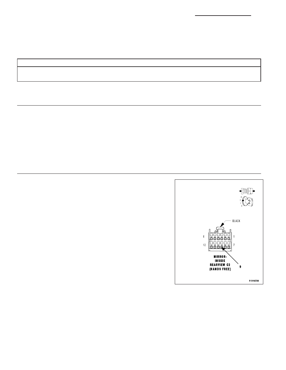
CHECK THE VOLTAGE OF THE (X730) VOICE RECOGNITION/PHONE SWITCH SIGNAL
Turn the ignition off.
Disconnect the Inside Rear View Mirror C2 harness connector.
Turn the ignition on.
With the scan tool, monitor the VR Phone Switch voltage.
While monitoring the VR Phone Switch voltage, momentarily connect a
jumper wire between (X730) Voice Recognition/Phone Switch Signal
circuit and ground.
NOTE: The scan tool sensor voltage should switch from above 4.7
volts when the jumper is not connected to below 0.6 volts when
the jumper is connected.
Does the sensor voltage switch from above 4.7 volts to below
0.6 volt as described?
Yes
>> Replace the Inside Rear View Mirror in accordance with the
service information.
Perform BODY VERIFICATION TEST – VER 1. (Refer to
BODY VERIFICATION TEST – VER 1).
No
>> Inspect the wiring and connectors for damage or shorted
circuits. If ok, replace and program the Hands Free Module
in accordance with the service information.
Perform BODY VERIFICATION TEST – VER 1. (Refer to BODY VERIFICATION TEST – VER 1).
8T - 28
NAVIGATION/TELECOMMUNICATION - ELECTRICAL DIAGNOSTICS
LX