Chrysler 300/300 Touring/300C, Dodge Magnum. Manual - part 792
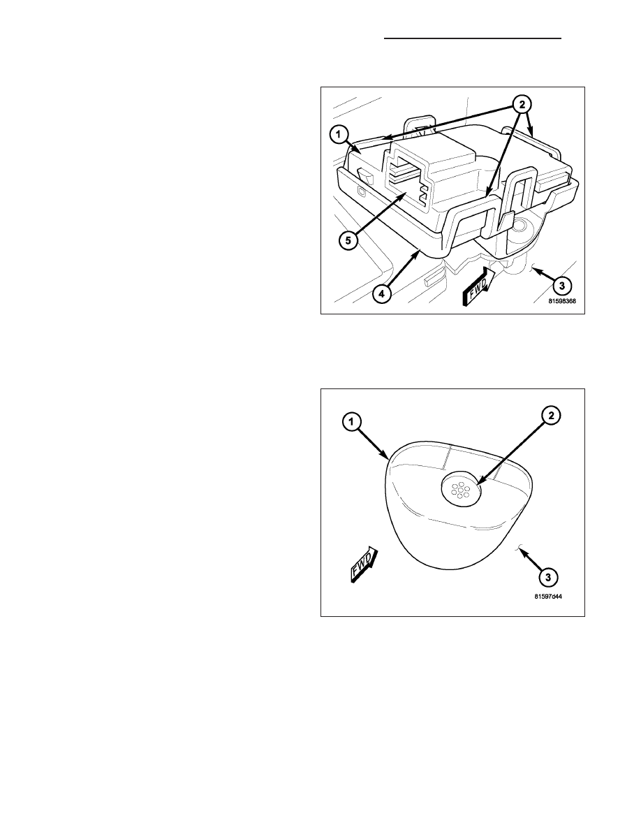
RECEIVER
1. Disconnect and isolate the battery negative cable.
2. Remove the overhead console from the headliner.
(Refer to 8 - ELECTRICAL/OVERHEAD CONSOLE
- REMOVAL).
3. Disconnect the electrical connector (5) on the
receiver housing.
4. Release the three latch features (2) of the mount-
ing bracket and disengage the receiver from the
bracket.
INSTALLATION
TRANSMITTER
1. Position the sensor on the inside of the C-pillar.
2. Install the two retaining screws.
3. Connect the electrical connector.
4. Install the C-pillar (Refer to 23 - BODY/INTERIOR/
C-PILLAR TRIM - INSTALLATION).
5. If installing the bezel, position the bezel (1) over
the transducer housing (2) of the intrusion sensor
transmitter and press it straight on until it snaps
into place against the C—pillar (3).
6. Reconnect the battery negative cable.
8Q - 136
VEHICLE THEFT SECURITY - SERVICE INFORMATION
LX