Chrysler 300/300 Touring/300C, Dodge Magnum. Manual - part 791


  Index      Chrysler     Chrysler 300/300 Touring/300C, Dodge Magnum - service repair manual


Search            


Content   ..  789  790  791  792   ..


Chrysler 300/300 Touring/300C, Dodge Magnum. Manual - part 791


INTRUSION MODULE - EXPORT

DESCRIPTION

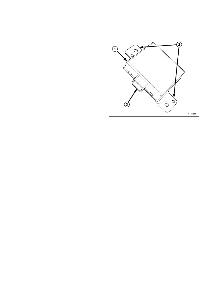
An intrusion module (1) is part of the premium version
of the Vehicle Theft Security System (VTSS). The pre-
mium version of the VTSS is only available in vehicles
built for certain markets, where the additional features
offered by this system are required. The intrusion
module is located in the passenger compartment. This
unit is designed to work in conjunction with the intru-
sion sensor transmitter and intrusion sensor receiver
to provide interior motion detection and serves as the
interface between the Forward Control Module (FCM),
the

ElectroMechanical

Instrument

Cluster

(EMIC),

sometimes referred to as the Cab Compartment Node
(CCN), and the alarm siren.

The intrusion module has two integral mounts (2) that
are secured behind the passenger side instrument
panel, just above the glove box. Concealed within the
molded plastic housing is the circuitry of the module,
which includes a microprocessor. The module is con-
nected to the vehicle electrical system by a connector
of the body wire harness.

The intrusion module unit cannot be adjusted or repaired and, if faulty or damaged, it must be replaced.

OPERATION

The microprocessor in the intrusion module contains the motion detection logic circuits and controls all of the fea-
tures of the premium version of the Vehicle Theft Security System (VTSS). The module uses On-Board Diagnostics
(OBD) and can communicate with other modules in the vehicle as well as with a diagnostic scan tool using the
Controller Area Network (CAN) data bus. This method of communication is used by the module to communicate with
the Forward Control Module (FCM) and the ElectroMechanical Instrument Cluster (EMIC), sometimes referred to as
the Cab Compartment Node (CCN). The module also communicates with the alarm siren over a dedicated serial
bus circuit.

The intrusion module microprocessor continuously monitors inputs from the intrusion sensor transmitter and receiver
as well as inputs from the EMIC/CCN and the alarm siren module. The module energizes the intrusion sensor trans-
mitter, which transmits ultrasonic signals into the vehicle cabin through a transmit transducer, then monitors the
current draw of the transmitter to detect problems with the transmitter and transmitter circuits. The module also
energizes the intrusion sensor receiver, which listens to the ultrasonic signals through a receive transducer as they
bounce off of objects in the vehicle interior, then monitors the current draw of the receiver for data signals and to
detect problems with the receiver and receiver circuits. If an object is moving in the interior, a detection circuit in the
module senses this movement through the modulation of the returning data signals from the receiver.

If movement is detected, the intrusion module sends an electronic message to the FCM over the CAN data bus to
flash the exterior lighting and sends another message to the alarm siren module over the dedicated serial bus line
to sound the siren. When the EMIC/CCN or FCM detect a breach in the perimeter protection through a door or hood
ajar switch input, they send an electronic message to the intrusion module and the module sends a message to the
FCM to flash the exterior lighting and a message to the alarm siren module to sound the siren. The module also
monitors message inputs from the alarm siren module for siren battery or siren input/output circuit tamper alerts,
and siren battery condition alerts, then sets active and stored Diagnostic Trouble Codes (DTC) for any monitored
system faults it detects. An active fault only remains for the current ignition switch cycle, while a stored fault causes
a DTC to be stored in memory by the module. If a fault does not recur for 50 ignition cycles, the module will auto-
matically erase the stored DTC.

The intrusion module receives constant battery voltage (when armed), and is grounded at all times through a hard
wired remote ground point. These connections allow the module to remain operational, regardless of the ignition
switch position. Use a diagnostic scan tool and refer to the appropriate diagnostic information for proper diagnosis
of the system.

8Q - 132

VEHICLE THEFT SECURITY - SERVICE INFORMATION

LX

REMOVAL

1. Disconnect and isolate the battery negative cable.

2. Remove the glove box (Refer to 23 - BODY/INSTRUMENT PANEL/GLOVE BOX - REMOVAL).

3. Reach up behind the instrument panel and remove the two retaining screws to the intrusion module.

4. Disconnect the electrical connector to the intrusion Module.

5. Remove the module from the instrument panel.

INSTALLATION

1. Position the intrusion module on the passenger side of the instrument panel and connect the electrical connector.

2. Install and tighten the two fasteners that secure the module to the instrument panel.

3. Install the glove box (Refer to 23 - BODY/INSTRUMENT PANEL/GLOVE BOX - INSTALLATION).

4. Connect the battery negative cable.

LX

VEHICLE THEFT SECURITY - SERVICE INFORMATION

8Q - 133

INTRUSION SENSOR - EXPORT

DESCRIPTION

TRANSMITTER

An intrusion sensor transmitter (2) is part of the pre-
mium version of the Vehicle Theft Security System
(VTSS). The premium version of the VTSS is only
available in vehicles built for certain markets, where
the additional features offered by this system are
required. This unit is designed to work in conjunction
with the intrusion sensor receiver to provide interior
motion detection inputs to the intrusion module, which
serves as the interface between the Forward Control
Module

(FCM),

the

ElectroMechanical

Instrument

Cluster (EMIC), sometimes referred to as the Cab
Compartment Node (CCN), and the alarm siren.

The transmitter is located in the passenger compart-
ment, where it is concealed behind the right C-pillar.
The trim bezel has a small round opening that faces
the front of the vehicle through which the transducer is
aimed. Concealed within the molded plastic transmitter
housing is the circuitry of the transmitter which
includes an ultrasonic transmit transducer (1).

The intrusion sensor transmitter cannot be adjusted or repaired and, if faulty or damaged, it must be replaced. The
transmitter mounting bracket is serviced as a unit with the headliner. The transducer trim bezel is available for sep-
arate service replacement.

RECEIVER

An intrusion sensor receiver (1) is part of the premium
version of the Vehicle Theft Security System (VTSS).
The premium version of the VTSS is only available in
vehicles built for certain markets, where the additional
features offered by this system are required. This unit
is designed to work in conjunction with the intrusion
sensor transmitter to provide interior motion detection
inputs to the intrusion module, which serves as the
interface between the Forward Control Module (FCM),
the

ElectroMechanical

Instrument

Cluster

(EMIC),

sometimes referred to as the Cab Compartment Node
(CCN), and the alarm siren.

The receiver is located in the passenger compartment,
where it is concealed behind the right front corner of
the overhead console housing and engages three
latch tabs integral to the receiver housing. The ultra-
sonic receiver transducer (2) is aimed through a small
dedicated round opening in the overhead console for-
ward of the reading lamps and is the only evidence of
the receiver that is visible from the passenger compartment.

Concealed within the receiver housing is the circuitry which includes the receive transducer. The receiver is con-
nected to the vehicle electrical system wire harness that is integral to the headliner.

The intrusion sensor receiver cannot be adjusted or repaired and, if faulty or damaged, it must be replaced. The
receiver mounting bracket is serviced as a unit with the overhead console.

8Q - 134

VEHICLE THEFT SECURITY - SERVICE INFORMATION

LX

OPERATION

TRANSMITTER

The intrusion sensor transmitter operates only when it is energized by the intrusion module. The transmitter gener-
ates ultrasonic signals into the vehicle cabin through a transmit transducer. Then the intrusion sensor receiver lis-
tens to the returning signals as they bounce off of objects in the vehicle interior and provides input signals to the
intrusion module. If an object is moving in the interior, a detection circuit in the intrusion module senses this move-
ment through the modulation of the returning signals that occur due to the Doppler effect. The intrusion module
monitors the current draw of the transmitter circuits to determine the condition of the transmitter and, if the draw is
too high or too low, it will store a Diagnostic Trouble Code (DTC) for any fault that is detected.

Use a diagnostic scan tool and refer to the appropriate diagnostic information for diagnosis and testing of the sys-
tem.

RECEIVER

The intrusion sensor receiver operates only when it is energized by the intrusion module. The receiver monitors
ultrasonic signals generated in the vehicle cabin by the intrusion sensor transmitter through a receive transducer.
The receiver listens to the ultrasonic signals as they bounce off of objects in the vehicle interior and provides input
signals to the intrusion module. If an object is moving in the interior, a detection circuit in the intrusion module
senses this movement through the modulation of the returning signals that occur due to the Doppler effect. The
intrusion module monitors the current draw of the receiver circuits to determine the condition of the receiver and, if
the draw is too high or too low, it will store a Diagnostic Trouble Code (DTC) for any fault that is detected.

Use a diagnostic scan tool and refer to the appropriate diagnostic information for diagnosis and testing of the sys-
tem.

REMOVAL

TRANSMITTER

1. Disconnect and isolate the battery negative cable.

2. If replacing the bezel, pull the bezel (1) inboard

from the C-pillar (3), or use a trim stick or equiva-
lent to unsnap it from the transducer housing (2) of
the intrusion sensor transmitter.

3. Remove the C-pillar trim panel (Refer to 23 -

BODY/INTERIOR/C-PILLAR TRIM - REMOVAL).

4. Remove the two retaining screws from the C-pillar

and remove the sensor.

LX

VEHICLE THEFT SECURITY - SERVICE INFORMATION

8Q - 135


Content   ..  789  790  791  792   ..