Chrysler 300/300 Touring/300C, Dodge Magnum. Manual - part 788


  Index      Chrysler     Chrysler 300/300 Touring/300C, Dodge Magnum - service repair manual


Search            


Content   ..  786  787  788  789   ..


Chrysler 300/300 Touring/300C, Dodge Magnum. Manual - part 788


3.

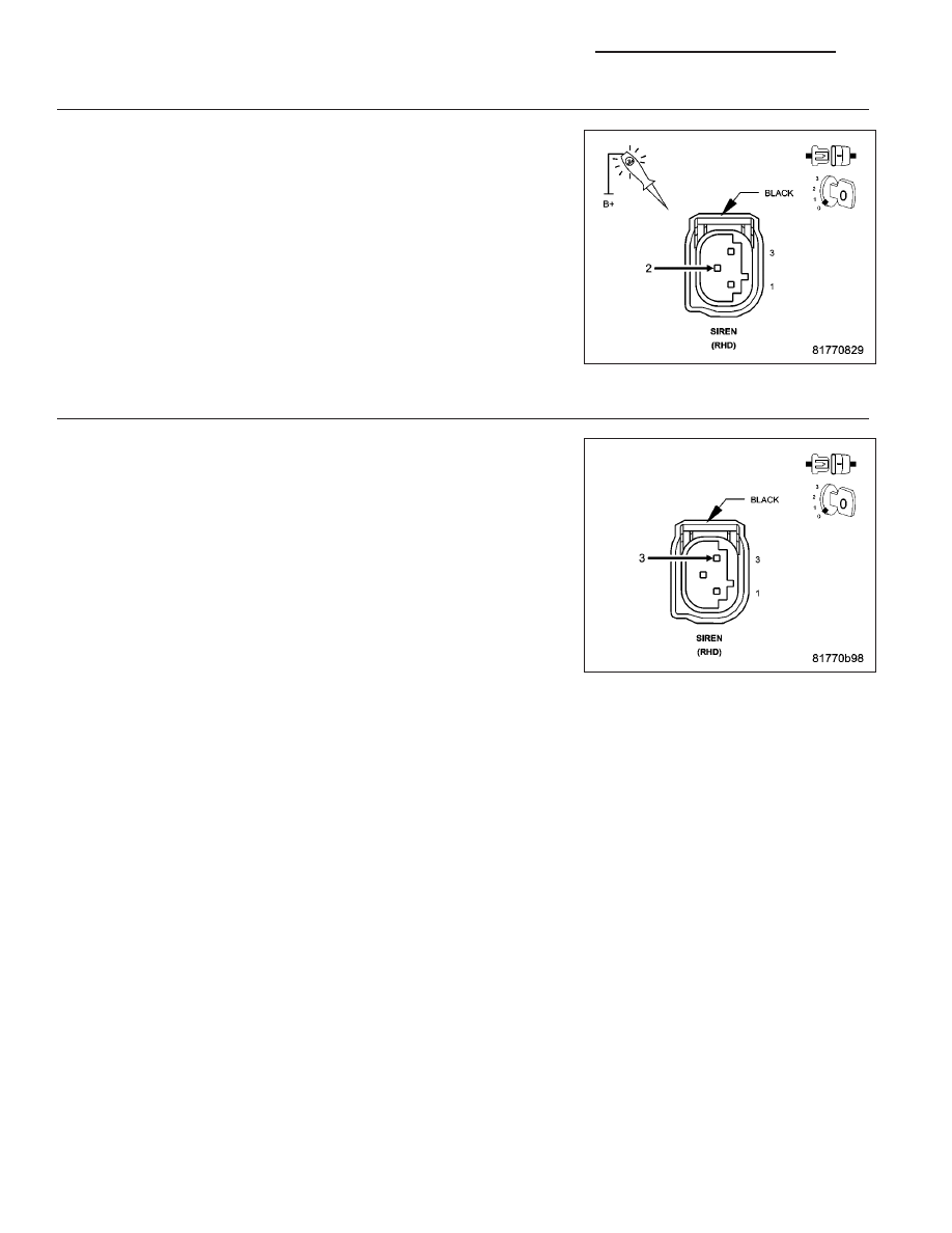
(Z904) GROUND CIRCUIT

Using a 12-volt test light connected to 12-volts, check the (Z904)
Ground circuit at the siren connector.

Does the test light illuminate brightly?

Yes

>> Go To 4

No

>> Repair the (Z904) Ground circuit for an open.

Perform BODY VERIFICATION TEST - 1A. (Refer to 8 -
ELECTRICAL/ELECTRONIC

CONTROL

MODULES

-

STANDARD PROCEDURE)

4.

FAULTY SIREN

Use the DRBIII

T

and set up as follows:

Use the Scope input cable CH7058, Cable to Probe adapter CH7062,
and the red and black test probes.

Connect the scope input cable to the channel one connector on the
DRBIII

T

. Attach the red and black leads and the cable to probe adapter

to the scope input cable.

Select DRBIII

T

Stand-alone.

Select lab scope.

Select Live.

Select 12 volt square wave.

Press F2 for Scope.

Press F2 and use the down arrow to set voltage range to 20 volts.
Press F2 again when complete.

Disconnect the Siren connector.

Connect the black lead to the chassis ground. Connect the red lead to the (D96) Siren Signal Control circuit in the
Siren connector.

Close all doors and arm the VTSS.

Observe the voltage displayed on the DRBIII

T

Lab Scope.

Is there a voltage square wave present 1 to 2 seconds?

Yes

>> Connect a known good siren and try to reset the DTC. If the DTC does not reset the original siren

needs to be replaced. If the DTC does reset replace the Intrusion Transceiver Module in accordance
with the Service Information.

Perform BODY VERIFICATION TEST - VER 1. (Refer to 8 - ELECTRICAL/ELECTRONIC CONTROL
MODULES - STANDARD PROCEDURE)

No

>> Go To 5

8Q - 120

VEHICLE THEFT SECURITY - ELECTRICAL DIAGNOSTICS

LX

5.

(D96) SIREN SIGNAL CONTROL CIRCUIT SHORT TO BATTERY

Disconnect the Siren harness connector.

Measure the voltage of the (D96) Siren Signal Control circuit.

Is there any voltage present?

Yes

>> Repair the (D96) Siren Signal Control circuit for a short to

voltage.Perform BODY VERIFICATION TEST - 1A. (Refer
to 8 - ELECTRICAL/ELECTRONIC CONTROL MODULES -
STANDARD PROCEDURE)

No

>> Go To 6

6.

(D96) SIREN SIGNAL CONTROL CIRCUIT SHORT TO GROUND

Disconnect the Siren harness connector.

Disconnect the Intrusion Transceiver Module harness connector.

Measure the resistance between ground and the (D96) Siren Signal
Control circuit.

Is the resistance above 5.0 ohms?

Yes

>> Go To 7

No

>> Repair the (D96) Siren Signal Control circuit for a short to

ground.

Perform BODY VERIFICATION TEST - 1A. (Refer to 8 -
ELECTRICAL/ELECTRONIC

CONTROL

MODULES

-

STANDARD PROCEDURE)

7.

(D96) SIREN SIGNAL CONTROL CIRCUIT OPEN

Disconnect the Intrusion Transceiver Module harness connector.

Measure the resistance of the (D96) Siren Signal Control circuit
between the Intrusion Transceiver Module and the Siren connector.

Is the resistance below 5.0 ohms?

Yes

>> Replace the Intrusion Transceiver Module in accordance

with the Service Information.

Perform BODY VERIFICATION TEST - VER 1. (Refer to 8 -
ELECTRICAL/ELECTRONIC

CONTROL

MODULES

-

STANDARD PROCEDURE)

No

>> Repair the (D96) Siren Signal Control circuit for an open.

Perform BODY VERIFICATION TEST - 1A. (Refer to 8 -
ELECTRICAL/ELECTRONIC

CONTROL

MODULES

-

STANDARD PROCEDURE)

LX

VEHICLE THEFT SECURITY - ELECTRICAL DIAGNOSTICS

8Q - 121

STANDARD PROCEDURE

8Q - 122

VEHICLE THEFT SECURITY - ELECTRICAL DIAGNOSTICS

LX

SKREEM/SKIM VERIFICATION

For a complete wiring diagram Refer to Section 8W.

Diagnostic Test

1.

SKREEM/SKIM VERIFICATION

NOTE: When entering the PIN, care should be taken because the SKREEM will only allow 3 consecutive
attempts to enter the correct PIN. If 3 consecutive incorrect PIN’s are entered the SKREEM will Lock Out the
scan tool. To exit Lock Mode, the ignition key must remain the Run position for I hour. All accessories must
be off. A battery charger connected to the battery during this time period is recommended.

NOTE: On vehicles equipped with a premium Tire Pressure Monitoring (TPM) system, when the SKREEM
and/or the spare tire pressure sensor is replaced with a new unit, a diagnostic scan tool MUST be used to
run a routine that allows the SKREEM to be programmed with the ID number and location of the spare tire
pressure sensor mounted in the wheel of the spare tire. Follow the programming steps outlined in the diag-
nostic scan tool for “Learn Spare Tire Sensor ID” under “Miscellaneous Functions” for the “WCM/Wireless
Control Module” menu item as appropriate. In addition, if the SKREEM is replaced, the spare tire must be
dismounted from its wheel to access and note the ID number on the spare tire pressure sensor so that the
ID code for that sensor can be programmed into the new SKREEM.

1. Reconnect the previously disconnected components and connectors.

2. Obtain the vehicle’s unique Personal Identification Number (PIN) assigned to it’s original SKREEM. This num-
ber can be obtained from the vehicle invoice or from the DaimlerChrysler Customer Center (Phone 1-800-992-
1997).

3. With the scan tool, select Miscellaneous Functions, WCM/Wireless Control Module. Then select the desired
procedure and follow the display on the scan tool.

4. If the vehicle is equipped with Tire Pressure Monitoring System program the Palcard Pressure Values into the
WCM/SKREEM.

5. Ensure all the customer’s key have been programmed into the new module if necessary.

6. With the scan tool, ease all DTCs. Perform 5 ignition key cycles, leaving the key on for at least 90 seconds
per cycle.

7. With the scan tool, read SKREEM DTC(s).

8.

NOTE: If this vehicle is equipped with a Steering Column Lock Module, it must be replaced along with the
SKREEM.

Are there any SKREEM DTC(s) present?

Yes

>> Repair not complete, refer to the appropriate symptom.

No

>> Repair is complete.

LX

VEHICLE THEFT SECURITY - ELECTRICAL DIAGNOSTICS

8Q - 123


Content   ..  786  787  788  789   ..