Chrysler 300/300 Touring/300C, Dodge Magnum. Manual - part 786


  Index      Chrysler     Chrysler 300/300 Touring/300C, Dodge Magnum - service repair manual


Search            


Content   ..  784  785  786  787   ..


Chrysler 300/300 Touring/300C, Dodge Magnum. Manual - part 786


3.

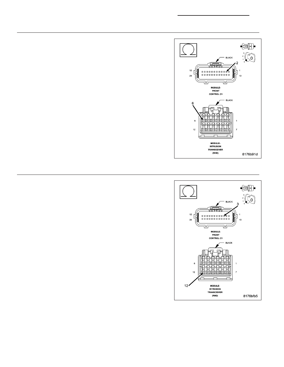
(D55) CAN B BUS (+) CIRCUIT OPEN

Turn the ignition off.

Disconnect the negative battery cable.

Disconnect the Intrusion Transceiver Module connector.

Disconnect the Front Control Module C1 connector.

Measure the resistance of the (D55) CAN B Bus (+) circuit between the
Front Control Module C1 connector and the Intrusion Transceiver Mod-
ule connector.

Is the resistance below 2.0 ohms?

Yes

>> Go To 4

No

>> Repair the (D55) CAN B Bus (+) circuit for an open.

Perform BODY VERIFICATION TEST - VER 1. (Refer to 8 -
ELECTRICAL/ELECTRONIC

CONTROL

MODULES

-

STANDARD PROCEDURE)

4.

(D54) CAN B BUS (–) CIRCUIT OPEN

Measure the resistance of the (D54) CAN B Bus (–) circuit between the
Front Control Module C1 connector and the Intrusion Transceiver Mod-
ule connector.

Is the resistance below 2.0 ohms?

Yes

>> Replace the Intrusion Transceiver Module in accordance

with the service information.

Perform BODY VERIFICATION TEST - VER 1. (Refer to 8 -
ELECTRICAL/ELECTRONIC

CONTROL

MODULES

-

STANDARD PROCEDURE)

No

>> Repair the (D54) CAN B Bus (–) circuit for an open.

Perform BODY VERIFICATION TEST - VER 1. (Refer to 8 -
ELECTRICAL/ELECTRONIC

CONTROL

MODULES

-

STANDARD PROCEDURE)

8Q - 112

VEHICLE THEFT SECURITY - ELECTRICAL DIAGNOSTICS

LX

U0141-LOST COMMUNICATION WITH FRONT CONTROL MODULE

For a complete wiring diagram Refer to Section 8W.

(Refer to 8 - ELECTRICAL/ELECTRONIC CONTROL MODULES - DIAGNOSIS AND TESTING) for the diagnostic
test procedure.

U0146-LOST COMMUNICATION WITH CENTRAL GATEWAY

For a complete wiring diagram Refer to Section 8W.

(Refer to 8 - ELECTRICAL/ELECTRONIC CONTROL MODULES - DIAGNOSIS AND TESTING) and perform the
U0141-Lost Communication With Front Control Module test for the diagnostic test procedure.

U0151-LOST COMMUNICATION WITH OCCUPANT RESTRAINT CONTROLLER

For a complete wiring diagram Refer to Section 8W.

(Refer to 8 - ELECTRICAL/ELECTRONIC CONTROL MODULES - DIAGNOSIS AND TESTING) for the diagnostic
test procedure.

U0154-LOST COMMUNICATION WITH OCCUPANT CLASSIFICATION MODULE

For a complete wiring diagram Refer to Section 8W.

(Refer to 8 - ELECTRICAL/ELECTRONIC CONTROL MODULES - DIAGNOSIS AND TESTING) for the diagnostic
test procedure.

U0155-LOST COMMUNICATION WITH CLUSTER/CCN

For a complete wiring diagram Refer to Section 8W.

(Refer to 8 - ELECTRICAL/ELECTRONIC CONTROL MODULES - DIAGNOSIS AND TESTING) for the diagnostic
test procedure.

LX

VEHICLE THEFT SECURITY - ELECTRICAL DIAGNOSTICS

8Q - 113

U110D-LOST COMMUNICATION WITH SECURITY SIREN

For a complete wiring diagram Refer to Section 8W

8Q - 114

VEHICLE THEFT SECURITY - ELECTRICAL DIAGNOSTICS

LX

When Monitored:
Continuously while the VTSS is armed.

Set Condition:
If the Intrusion Transceiver Module does not receive messages from the Siren.

Possible Causes

INTERMITTENT CONDITION

(A117) FUSED B(+) (I.O.D.) CIRCUIT OPEN

(Z904) GROUND CIRCUIT OPEN

(D96) SIREN SIGNAL CONTROL CIRCUIT SHORT TO BATTERY

(D96) SIREN SIGNAL CONTROL CIRCUIT OPEN

(D96) SIREN SIGNAL CONTROL CIRCUIT SHORT TO GROUND

SIREN

INTRUSION TRANSCEIVER MODULE

Diagnostic Test

1.

INTERMITTENT DTC

With the scan tool, erase the current Intrusion Transceiver Module DTC’s.

Turn the ignition off.

Arm the VTSS and wait 1 minute.

Disarm the VTSS and turn the ignition on.

Does the scan tool display the same DTC?

Yes

>> Go To 2

No

>> The condition that caused this symptom is currently not present. Inspect the related wiring harness for

a possible intermittent condition. Look for any chafed, pierced, pinched or partially broken wires.

Perform BODY VERIFICATION TEST - VER 1. (Refer to 8 - ELECTRICAL/ELECTRONIC CONTROL
MODULES - STANDARD PROCEDURE)

2.

(A117) FUSED B(+) (I.O.D.) CIRCUIT OPEN

Gain access to the VTSS Siren.

Disconnect the Siren connector.

Using a 12-volt test light connected to ground, check the (A117) Fused
B(+) (I.O.D.) circuit in the Siren connector.

Does the test light illuminate brightly?

Yes

>> Go To 3

No

>> Repair the (A117) Fused B(+) (I.O.D.) circuit for an open.

Perform BODY VERIFICATION TEST - VER 1. (Refer to 8 -
ELECTRICAL/ELECTRONIC

CONTROL

MODULES

-

STANDARD PROCEDURE)

LX

VEHICLE THEFT SECURITY - ELECTRICAL DIAGNOSTICS

8Q - 115


Content   ..  784  785  786  787   ..