Chrysler 300/300 Touring/300C, Dodge Magnum. Manual - part 732
For a complete wiring diagram Refer to Section 8W.
•
When Monitored:
The Occupant Restraint Controller (ORC) continuously communicates with the Left Side Impact Sensor 1 over
the sensor signal circuit. The sensor communication and on board diagnostics are powered by the ORC signal.
•
Set Condition:
This code will set, if the ORC and the Left Side Impact Sensor 1 do not establish and maintain valid data
communications.
Possible Causes
(R13) SIGNAL CIRCUIT SHORTED TO BATTERY
(R13) SIGNAL CIRCUIT SHORTED TO GROUND
(R13, R15) LEFT SIDE IMPACT SENSOR 1 CIRCUITS SHORTED TOGETHER
(R15) LEFT SIDE IMPACT SENSOR 1 GROUND CIRCUIT OPEN
(R13) LEFT SIDE IMPACT SENSOR 1 SIGNAL CIRCUIT OPEN
ORC, LEFT SIDE IMPACT SENSOR 1
Diagnostic Test
1.
VERIFY THAT DTC U0172-LOST COMMUNICATION W/LEFT SIDE SATELLITE ACCELERATION SENSOR 1
IS ACTIVE
NOTE: Ensure the battery is fully charged.
NOTE: When reconnecting Airbag system components, the ignition must be turned off and the battery must
be disconnected.
Turn the ignition on.
With the scan tool, read ORC DTCs.
Does the scan tool display active: U0172-LOST COMMUNICATION W/LEFT SIDE IMPACT SENSOR 1?
Yes
>> Go To 2
No
>> Go To 9
2.
CHECK THE (R13, R15) LEFT SIDE IMPACT SENSOR 1 SIGNAL AND GROUND CIRCUITS FOR A SHORT
TO BATTERY
WARNING: To avoid personal injury or death, turn the ignition off,
disconnect the battery and wait two minutes before proceeding.
Disconnect the Left Side Impact Sensor 1 connector.
Disconnect the ORC connector.
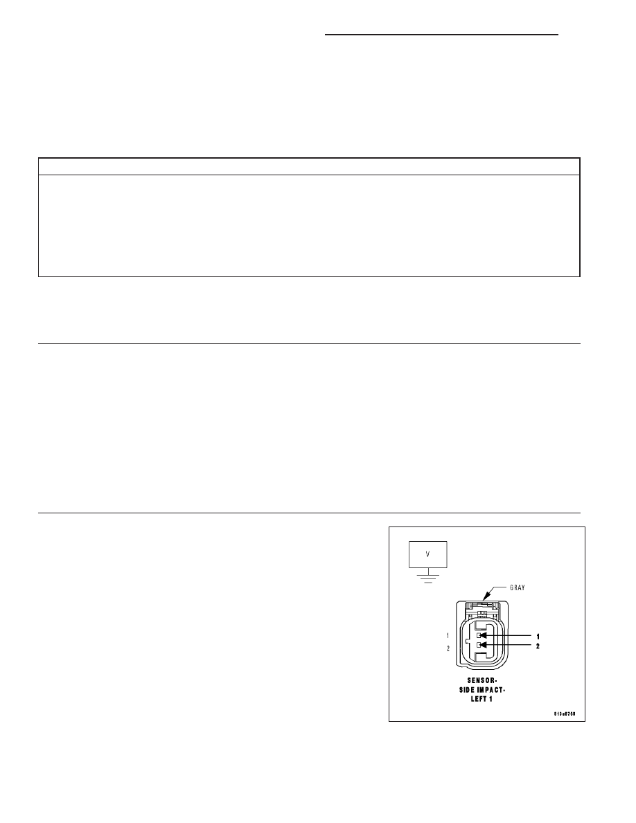
WARNING: To avoid personal injury or death, turn the ignition on,
then reconnect the battery.
Measure the voltage of the (R13) Left Side Impact Sensor 1 Signal cir-
cuit and (R15) Sensor Ground circuit at the Left Side Impact Sensor 1
connector and ground.
Is there any voltage present?
Yes
>> Repair the (R13, R15) Left Side Impact Sensor 1 circuits
for a short to battery.
Perform the ORC VERIFICATION TEST - VER 1.
No
>> Go To 3
8O - 334
RESTRAINTS - ELECTRICAL DIAGNOSTICS
LX