Chrysler 300/300 Touring/300C, Dodge Magnum. Manual - part 629
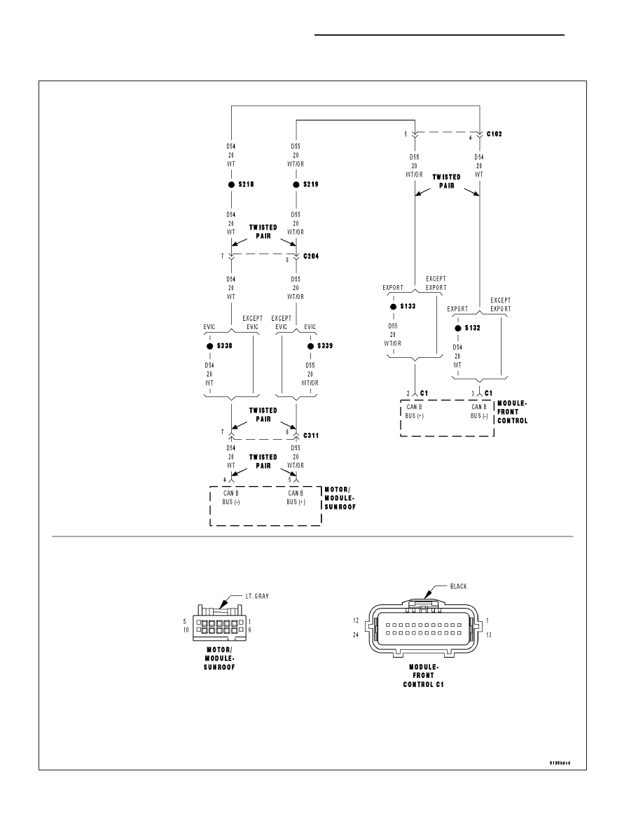
U0019–CAN B BUS
For a complete wiring diagram Refer to Section 8W.
8N - 214
POWER TOP - ELECTRICAL DIAGNOSIS
LX
|
|
|
U0019–CAN B BUS For a complete wiring diagram Refer to Section 8W. 8N - 214 POWER TOP - ELECTRICAL DIAGNOSIS LX |