Chrysler 300/300 Touring/300C, Dodge Magnum. Manual - part 458


  Index      Chrysler     Chrysler 300/300 Touring/300C, Dodge Magnum - service repair manual


Search            


Content   ..  456  457  458  459   ..


Chrysler 300/300 Touring/300C, Dodge Magnum. Manual - part 458


When Monitored:
With the ignition on or off and with the FCM awake.

Set Condition:
The Front Control Module will set this DTC within 2 seconds if the ignition unlock run/start circuit voltage is not
what the expected value should be.

Possible Causes

(F902) IGNITION UNLOCK RUN START CIRCUIT OPEN

(F902) IGNITION UNLOCK RUN START CIRCUIT SHORTED TO VOLTAGE

SHIFTER LEVER ASSEMBLY

FRONT CONTROL MODULE

Diagnostic Test

1.

CHECK FOR ACTIVE DTC

With the scan tool, read the active DTC’s.

Cycle the ignition switch from off to on, leaving the ignition on for a minimum of 90 seconds then turn the ignition
off.

With the scan tool, read the active DTC’s.

Does the scan tool display this DTC as active?

Yes

>> Go To 2

No

>> If the DTC is stored, check for an intermittent condition. Visually inspect the related wiring harness con-

nectors. Look for broken, bent, pushed out, or corroded terminals.

2.

(F902) IGNITION UNLOCK RUN START CIRCUIT SHORTED TO VOLTAGE

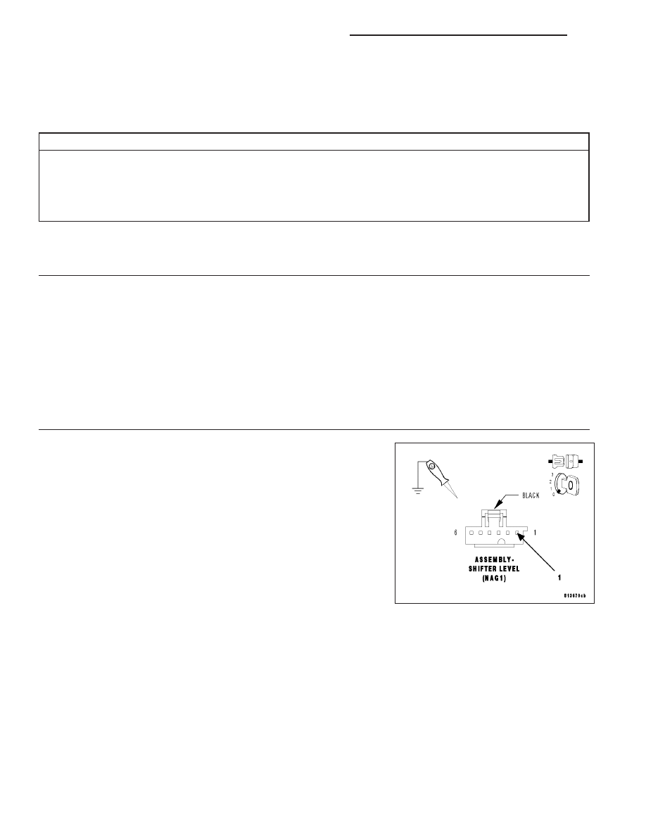
Disconnect the Shifter Lever Assembly harness connector.

Cycle the ignition switch from off to on then back to off.

NOTE: The ignition switch must be in the off position when per-
forming the following step.
Using a 12–volt test light connected to ground, check the (F902) Igni-
tion Unlock Run Start circuit.

Does the test light illuminate brightly?

Yes

>> Repair the (F902) Ignition Unlock Run Start circuit for a

short to voltage.

Perform BODY VERIFICATION TEST – VER 1. (Refer to
BODY VERIFICATION TEST – VER 1).

No

>> Go To 3

8I - 10

IGNITION SYSTEM - ELECTRICAL DIAGNOSTICS

LX

3.

SHIFTER LEVER ASSEMBLY

Turn the ignition on.

With the test light still connected from the previous step, check the
(F902) Ignition Unlock Run Start circuit.

Does the test light illuminate brightly?

Yes

>> Replace the Shifter Lever Assembly in accordance with the

service information.

Perform BODY VERIFICATION TEST – VER 1. (Refer to
BODY VERIFICATION TEST – VER 1).

No

>> Go To 4

4.

(F902) IGNITION UNLOCK RUN START CIRCUIT OPEN

Turn the ignition off.

Remove the FCM from the IPM.

Measure the resistance of the (F902) Ignition Unlock Run Start circuit
between the Shifter Lever Assembly and the FCM-PDM connector.

Is the resistance below 5.0 ohms?

Yes

>> Inspect the wiring and connectors for damage or shorted

circuits. If ok, replace and program the Front Control Mod-
ule in accordance with the service information.

Perform BODY VERIFICATION TEST – VER 1. (Refer to
BODY VERIFICATION TEST – VER 1).

No

>> Repair the (F902) Ignition Unlock Run Start circuit for an

open.

Perform BODY VERIFICATION TEST – VER 1. (Refer to
BODY VERIFICATION TEST – VER 1).

LX

IGNITION SYSTEM - ELECTRICAL DIAGNOSTICS

8I - 11

B211E–IGNITION RUN/ACC/PAD CONTROL CIRCUIT LOW

For a complete wiring diagram Refer to Section 8W.

8I - 12

IGNITION SYSTEM - ELECTRICAL DIAGNOSTICS

LX

When Monitored:
With the ignition on.

Set Condition:
The Front Control Module will set this DTC within 500ms if the (P307) Accessory Delay Relay Control circuit is
open or shorted to ground.

Possible Causes

(P307) ACCESSORY DELAY RELAY CONTROL CIRCUIT OPEN

(P307) ACCESSORY DELAY RELAY CONTROL CIRCUIT SHORTED TO GROUND

ACCESSORY DELAY RELAY

FRONT CONTROL MODULE

Diagnostic Test

1.

CHECK FOR ACTIVE DTC

With the scan tool, read the active DTC’s.

Cycle the ignition switch from off to on, leaving the ignition on for a minimum of 90 seconds.

With the scan tool, read the active DTC’s.

Does the scan tool display this DTC as active?

Yes

>> Go To 2

No

>> If the DTC is stored, check for an intermittent condition. Visually inspect the related wiring harness con-

nectors. Look for broken, bent, pushed out, or corroded terminals.

2.

ACCESSORY DELAY RELAY

Turn the ignition off.

Install a substitute relay in place of the original Accessory Delay Relay.

Cycle the ignition switch from off to on, leaving the ignition on for a minimum of 90 seconds.

With the scan tool, read the active FCM DTC’s.

Does the scan tool display this DTC as active?

Yes

>> Go To 3

No

>> Replace the original Accessory Delay Relay.

Perform BODY VERIFICATION TEST – VER 1. (Refer to BODY VERIFICATION TEST – VER 1).

LX

IGNITION SYSTEM - ELECTRICAL DIAGNOSTICS

8I - 13


Content   ..  456  457  458  459   ..