Chrysler 300/300 Touring/300C, Dodge Magnum. Manual - part 421


  Index      Chrysler     Chrysler 300/300 Touring/300C, Dodge Magnum - service repair manual


Search            


Content   ..  419  420  421  422   ..


Chrysler 300/300 Touring/300C, Dodge Magnum. Manual - part 421


5.7L

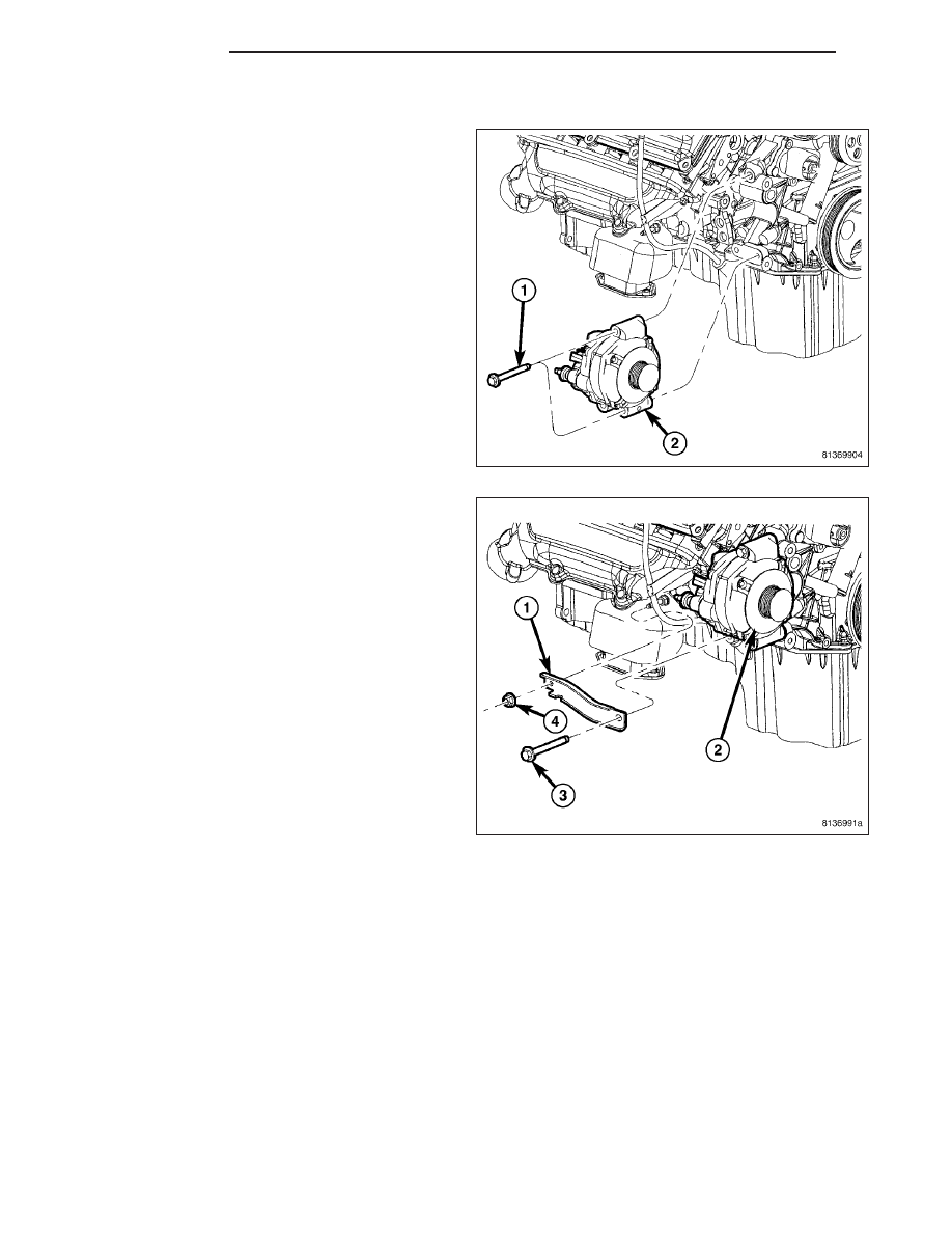
1. Position generator (2) to engine and install 2

mounting bolts (1).

2. Tighten bolts. Refer to Torque Specifications.

3. Position support bracket (1) to generator and install

bolt (3) and nut (4). Tighten bolt / nut. Refer to
Torque Specifications.

4. Snap field wire connector into rear of generator.

5. Install B+ terminal eyelet to generator output stud. Tighten mounting nut. Refer to Torque Specifications.

6. Lower vehicle.

CAUTION: Never force a belt over a pulley rim using a screwdriver. The synthetic fiber of the belt can be
damaged.

CAUTION: When installing a serpentine accessory drive belt, the belt MUST be routed correctly. The water
pump may be rotating in the wrong direction if the belt is installed incorrectly, causing the engine to over-
heat. Refer to belt routing label in engine compartment, or refer to Belt Schematics in 7, Cooling System.

7. Install generator drive belt. Refer to 7, Cooling System for procedure.

8. Install negative battery cable to battery.

8F - 70

CHARGING

LX

VOLTAGE REGULATOR

DESCRIPTION

The Electronic Voltage Regulator (EVR) is not a separate component. It is actually a voltage regulating circuit
located within the Powertrain Control Module (PCM). The EVR is not serviced separately. If replacement is neces-
sary, the PCM must be replaced.

OPERATION

The amount of DC current produced by the generator is controlled by EVR circuitry contained within the PCM. This
circuitry is connected in series with the generators second rotor field terminal and its ground.

Voltage is regulated within the PCM on the NGC vehicles, to control the strength of the rotor magnetic field. The
EVR circuitry monitors system line voltage at the PDC and calculated battery temperature or inlet air temperature
sensor (refer to Inlet Air Temperature Sensor, if equipped, for more information ). It then determines a target charg-
ing voltage. If sensed battery voltage is lower than the target voltage, the PCM feeds the field winding until sensed
battery voltage is at the target voltage. A circuit in the PCM cycles the feed side of the generator field at 250 times
per second (250Hz), but has the capability to feed the field control wire 100% of the time (full field) to achieve the
target voltage. If the charging rate cannot be monitored (limp-in), a duty cycle of 20% is used by the PCM in order
to have some generator output. Also refer to Charging System Operation for additional information.

LX

CHARGING

8F - 71

STARTING

TABLE OF CONTENTS

page

page

STARTING

DESCRIPTION . . . . . . . . . . . . . . . . . . . . . . . . . . . . . . . . 73
OPERATION . . . . . . . . . . . . . . . . . . . . . . . . . . . . . . . . . . 73
DIAGNOSIS AND TESTING

DIAGNOSIS AND TESTING - STARTING

SYSTEM TEST . . . . . . . . . . . . . . . . . . . . . . . . . . . . 73

DIAGNOSIS AND TESTING - FEED CIRCUIT

RESISTANCE TEST . . . . . . . . . . . . . . . . . . . . . . . . 75

DIAGNOSIS AND TESTING - CONTROL

CIRCUIT TEST . . . . . . . . . . . . . . . . . . . . . . . . . . . . 76

SPECIFICATIONS

TORQUE . . . . . . . . . . . . . . . . . . . . . . . . . . . . . . . . . . . 78

STARTER MOTOR

REMOVAL

2.7L . . . . . . . . . . . . . . . . . . . . . . . . . . . . . . . . . . . . . . . 79

3.0L DIESEL . . . . . . . . . . . . . . . . . . . . . . . . . . . . . . . . 83
3.5L . . . . . . . . . . . . . . . . . . . . . . . . . . . . . . . . . . . . . . . 85
5.7L . . . . . . . . . . . . . . . . . . . . . . . . . . . . . . . . . . . . . . . 89
REMOVAL - 6.1L . . . . . . . . . . . . . . . . . . . . . . . . . . . . 90

INSTALLATION

2.7L . . . . . . . . . . . . . . . . . . . . . . . . . . . . . . . . . . . . . . . 91
3.0L diesel . . . . . . . . . . . . . . . . . . . . . . . . . . . . . . . . . . 95
3.5L . . . . . . . . . . . . . . . . . . . . . . . . . . . . . . . . . . . . . . . 97
INSTALLATION - 6.1L . . . . . . . . . . . . . . . . . . . . . . 101
5.7L . . . . . . . . . . . . . . . . . . . . . . . . . . . . . . . . . . . . . . 102

8F - 72

STARTING

LX

STARTING

DESCRIPTION

The starting system consists of:

Starter relay

Starter motor (including an integral starter solenoid)

Other components to be considered as part of starting system are:

Battery

Battery cables

Ignition switch and key lock cylinder

Clutch pedal position switch (manual transmission)

Park/neutral position switch (automatic transmission)

Wire harnesses and connections.

The Battery, Starting, and Charging systems operate in conjunction with one another, and must be tested as a com-
plete system. For correct operation of starting/charging systems, all components used in these 3 systems must per-
form within specifications. When attempting to diagnose any of these systems, it is important that you keep their
interdependency in mind.

The diagnostic procedures used in each of these groups include the most basic conventional diagnostic methods, to
the more sophisticated On-Board Diagnostics (OBD) built into the Powertrain Control Module (PCM). Use of an
induction-type milliampere ammeter, volt/ohmmeter, battery charger, carbon pile rheostat (load tester), and 12-volt
test lamp may be required.

OPERATION

These components form two separate circuits. A high amperage circuit that feeds the starter motor up to 300+
amps, and a control circuit that operates on less than 20 amps.

The PCM controls a double start over-ride safety that does not allow the starter to be engaged if the engine is
already running.

DIAGNOSIS AND TESTING

DIAGNOSIS AND TESTING - STARTING SYSTEM TEST

For circuit descriptions and diagrams, refer to the Wiring Diagrams.

WARNING: ON VEHICLES EQUIPPED WITH AIRBAGS, REFER TO THE PASSIVE RESTRAINT SYSTEMS
BEFORE ATTEMPTING STEERING WHEEL, STEERING COLUMN, OR INSTRUMENT PANEL COMPONENT
DIAGNOSIS OR SERVICE. FAILURE TO TAKE THE PROPER PRECAUTIONS COULD RESULT IN ACCIDEN-
TAL AIRBAG DEPLOYMENT AND POSSIBLE PERSONAL INJURY.

INSPECTION

Before removing any unit from the starting system for repair or diagnosis, perform the following inspections:

Battery - Visually inspect the battery for indications of physical damage and loose or corroded cable connec-
tions. Determine the state-of-charge and cranking capacity of the battery. Charge or replace the battery, if
required. Refer to the Battery section for more information.

Ignition Switch - Visually inspect the ignition switch for indications of physical damage and loose or corroded
wire harness connections.

Transmission Range Sensor or Park/Neutral Switch - Visually inspect the transmission range sensor for
indications of physical damage and loose or corroded wire harness connections.

Starter Relay - Visually inspect the starter relay for indications of physical damage and loose or corroded wire
harness connections.

Starter Motor - Visually inspect the starter motor for indications of physical damage and loose or corroded
wire harness connections.

LX

STARTING

8F - 73


Content   ..  419  420  421  422   ..