Chrysler 300/300 Touring/300C, Dodge Magnum. Manual - part 402
BATTERY FEED
A fused, direct battery feed to the TCM is used for continuous power. This battery voltage is necessary to retain
memory in the TCM. When the battery (B+) is disconnected, this memory is lost. When the battery (B+) is restored,
this memory loss is detected by the TCM and a Diagnostic Trouble Code (DTC) is set.
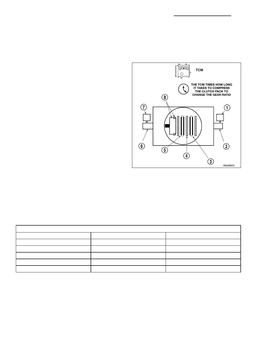
CLUTCH VOLUME INDEXES (CVI)
An important function of the TCM is to monitor Clutch
Volume Indexes (CVI). CVIs represent the volume of
fluid needed to compress a clutch pack.
The TCM monitors gear ratio changes by monitoring
the Input and Output Speed Sensors. The Input, or
Turbine Speed Sensor sends an electrical signal to
the TCM that represents input shaft rpm. The Output
Speed Sensor provides the TCM with output shaft
speed information.
By comparing the two inputs, the TCM can determine
transmission gear position. This is important to the
CVI calculation because the TCM determines CVIs by
monitoring how long it takes for a gear change to
occur.
Gear ratios can be determined by using the Scan Tool
and reading the Input/Output Speed Sensor values in
the “Monitors” display. Gear ratio can be obtained by
dividing the Input Speed Sensor value by the Output
Speed Sensor value.
For example, if the input shaft is rotating at 1000 rpm
and the output shaft is rotating at 500 rpm, then the
TCM can determine that the gear ratio is 2:1. In direct drive (3rd gear), the gear ratio changes to 1:1. The gear ratio
changes as clutches are applied and released. By monitoring the length of time it takes for the gear ratio to change
following a shift request, the TCM can determine the volume of fluid used to apply or release a friction element.
The volume of transmission fluid needed to apply the friction elements are continuously updated for adaptive con-
trols. As friction material wears, the volume of fluid need to apply the element increases.
Certain mechanical problems within the input clutch assembly can cause inadequate or out-of-range element vol-
umes. Also, defective Input/Output Speed Sensors and wiring can cause these conditions. The following chart iden-
tifies the appropriate clutch volumes and when they are monitored/updated:
CLUTCH VOLUMES
Clutch
When Updated
Proper Clutch Volume
L/R
2-1 or 3-1 downshift
45 to 134
2C
3-2 kickdown shift
25 to 85
OD
2-3 upshift
30 to 100
4C
3-4 upshift
30 to 85
UD
4-3 kickdown shift
30 to 100
SHIFT SCHEDULES
As mentioned earlier, the TCM has programming that allows it to select a variety of shift schedules. Shift schedule
selection is dependent on the following:
•
Shift lever position
•
Throttle position
•
Engine load
•
Fluid temperature
•
Software level
8E - 298
ELECTRONIC CONTROL MODULES - SERVICE INFORMATION
LX