Chrysler 300/300 Touring/300C, Dodge Magnum. Manual - part 2375


  Index      Chrysler     Chrysler 300/300 Touring/300C, Dodge Magnum - service repair manual


Search            


Content   ..  2373  2374  2375 


Chrysler 300/300 Touring/300C, Dodge Magnum. Manual - part 2375


3. Clean EGR tube where it joins EGR valve.

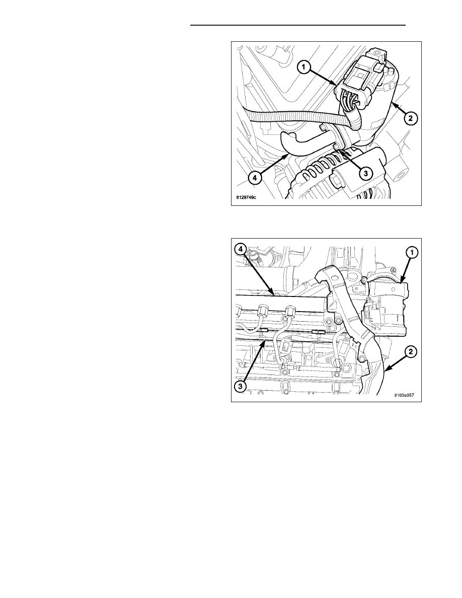
4. Position new gasket between EGR tube flange and

EGR valve assembly.

5. Install two bolts (3) connecting EGR tube (4) to

valve assembly (2). Tighten bolts. Refer to Torque
Specifications.

6. Connect electrical connector (1) to EGR solenoid

(2).

3.0L - DIESEL

1. Clean EGR valve sealing surfaces.

2. Lubricate the seal and install the EGR valve in

intake manifold. Tighten EGR valve retaining bolts
to 9 N·m (80 lbs.in).

3. Connect the EGR valve wiring harness connector.

4. Install engine cover. (Refer to 9 - ENGINE -

INSTALLATION)

5. Connect the negative battery cable. (Refer to 8 -

ELECTRICAL/BATTERY

SYSTEM/CABLES

-

INSTALLATION)

25 - 58

EXHAUST GAS RECIRCULATION

LX

SENSOR - EGR BACK PRESSURE

DESCRIPTION

The EGR back pressure sensor is located in the exhaust stream next to the EGR valve. The sensor determines the
exhaust pressure before the catalytic converter. The ECM uses the EGR back pressure sensor for engine protection
and exhaust gas turbocharger protection.

OPERATION

The exhaust gas effects a sensor membrane that acts against a potentiometer internal to the sensor. The potenti-
ometer changes the resistance value and thus influences the signal voltage of the sensor.

REMOVAL

1. Disconnect the negative battery cable.

2. Remove the engine cover.

3. Disconnect the sensor electrical sensor.

4. Remove the sensor.

INSTALLATION

1. Install the EGR back pressure sensor.

2. Connect the engine wiring harness electrical connector.

3. Install the engine cover.

4. Connect the negative battery cable.

LX

EXHAUST GAS RECIRCULATION

25 - 59

TASK MANAGER

DESCRIPTION

The PCM is responsible for efficiently coordinating the operation of all the emissions-related components. The PCM
is also responsible for determining if the diagnostic systems are operating properly. The software designed to carry
out these responsibilities is call the “Task Manager”.

OPERATION

The Task Manager determines when tests happen and when functions occur. Many of the diagnostic steps required
by OBD II must be performed under specific operating conditions. The Task Manager software organizes and pri-
oritizes the diagnostic procedures. The job of the Task Manager is to determine if conditions are appropriate for
tests to be run, monitor the parameters for a trip for each test, and record the results of the test. Following are the
responsibilities of the Task Manager software:

Test Sequence

MIL Illumination

Diagnostic Trouble Codes (DTCs)

Trip Indicator

Freeze Frame Data Storage

Similar Conditions Window

Test Sequence

In many instances, emissions systems must fail diagnostic tests more than once before the PCM illuminates the
MIL. These tests are known as ’two trip monitors.’ Other tests that turn the MIL lamp on after a single failure are
known as ’one trip monitors.’ A trip is defined as ’start the vehicle and operate it to meet the criteria necessary to
run the given monitor.’

Many of the diagnostic tests must be performed under certain operating conditions. However, there are times when
tests cannot be run because another test is in progress (conflict), another test has failed (pending) or the Task
Manager has set a fault that may cause a failure of the test (suspend).

Pending

Under some situations the Task Manager will not run a monitor if the MIL is illuminated and a fault is stored from
another monitor. In these situations, the Task Manager postpones monitors pending resolution of the original fault.
The Task Manager does not run the test until the problem is remedied.

For example, when the MIL is illuminated for an Oxygen Sensor fault, the Task Manager does not run the Catalyst
Monitor until the Oxygen Sensor fault is remedied. Since the Catalyst Monitor is based on signals from the Oxygen
Sensor, running the test would produce inaccurate results.

Conflict

There are situations when the Task Manager does not run a test if another monitor is in progress. In these situa-
tions, the effects of another monitor running could result in an erroneous failure. If this conflict is present, the mon-
itor is not run until the conflicting condition passes. Most likely the monitor will run later after the conflicting monitor
has passed.

For example, if the Fuel System Monitor is in progress, the Task Manager does not run the catalyst Monitor. Since
both tests monitor changes in air/fuel ratio and adaptive fuel compensation, the monitors will conflict with each other.

Suspend

Occasionally the Task Manager may not allow a two trip fault to mature. The Task Manager will suspend the matur-
ing of a fault if a condition exists that may induce an erroneous failure. This prevents illuminating the MIL for the
wrong fault and allows more precise diagnosis.

For example, if the PCM is storing a one trip fault for the Oxygen Sensor and the catalyst monitor, the Task Man-
ager may still run the catalyst Monitor but will suspend the results until the Oxygen Sensor Monitor either passes or
fails. At that point the Task Manager can determine if the catalyst system is actually failing or if an Oxygen Sensor
is failing.

LX

ON-BOARD DIAGNOSTICS

25 - 61


Content   ..  2373  2374  2375