Content .. 2358 2359 2360 2361 ..
Chrysler 300/300 Touring/300C, Dodge Magnum. Manual - part 2360
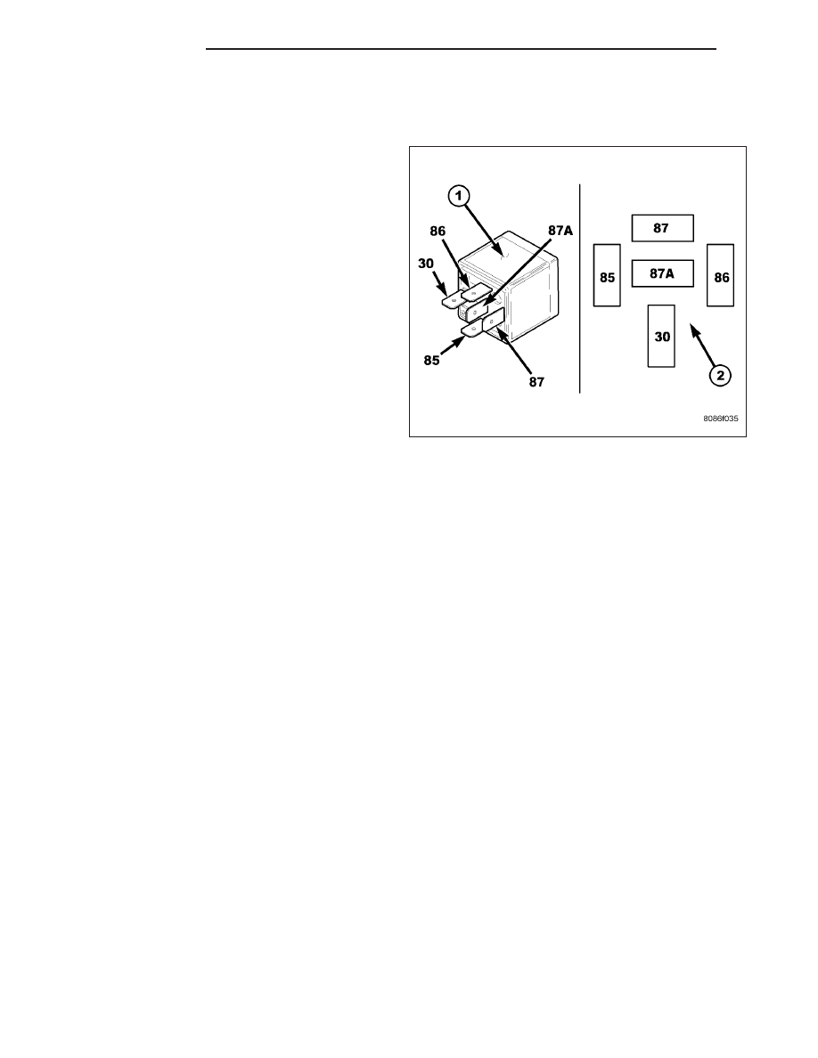
RELAY-HEATER UNIT
DESCRIPTION
Three relays (1) are used for the electric positive tem-
perature
coefficient
(PTC)
heater
system
when
equipped with the 3.0L diesel engine. The relays are
International
Standards
Organization
(ISO)-type
relays. Relays conforming to the ISO specifications
have common physical dimensions, current capacities,
terminal functions and patterns (2). The PTC relays
are electromechanical devices that switch fused bat-
tery current directly to the heating elements of the
PTC heater unit as determined by the engine control
module (ECM). The PTC relays are energized when
provided a ground path by the ECM and the front con-
trol (FCM).
The three PTC relays are located in the diesel acces-
sory fuse/relay block in the engine compartment.
OPERATION
The three ISO-standard relays (1) used for the electric positive temperature coefficient (PTC) heater system are
electromechanical switches that use a low current ASD power input to control the high current fused battery power
output to the PTC heater unit. On each relay, the movable, common feed relay contact is held against the fixed,
normally closed relay contact by spring pressure. When the electromagnetic relay coil is energized, it draws the
movable common feed relay contact away from the fixed, normally closed relay contact and, holds it against the
fixed, normally open relay contact. This action allows high current to flow to one or more of the heating elements of
the PTC heater.
When the relay coil is de-energized, spring pressure returns the movable relay contact back against the fixed, nor-
mally closed contact point. The resistor or diode is connected in parallel with the relay coil, and helps to dissipate
voltage spikes and electromagnetic interference that can be generated as the electromagnetic field of the relay coil
collapses.
The terminals for the PTC relays are connected to the vehicle electrical system through receptacles in the diesel
accessory fuse/relay block. The inputs and outputs of the PTC relays include:
•
Terminals (30) receive fused battery current at all times.
•
Terminals (85) are connected to a control circuit (ground circuit) of the engine control module (ECM) or front
control module (FCM) (depending on the relay).
•
Terminals (86) receive fused battery current through the ASD relay only when the ASD relay coil is energized.
•
Terminals (87) provide fused battery current to the PTC heating elements through the PTC relays only when
the PTC relay coil is energized.
•
Terminals (87A) are not connected to any circuit in this application, but provide battery current output only
when the PTC relay coil is de-energized.
The three PTC relays cannot be repaired and, if faulty or damaged, they must be replaced. Refer to the appropriate
wiring information for diagnosis and testing of the ISO-standard relays and for complete ECM, FCM and HVAC
wiring diagrams.
24 - 474
PLUMBING
LX