Chrysler 300/300 Touring/300C, Dodge Magnum. Manual - part 232


  Index      Chrysler     Chrysler 300/300 Touring/300C, Dodge Magnum - service repair manual


Search            


Content   ..  230  231  232  233   ..


Chrysler 300/300 Touring/300C, Dodge Magnum. Manual - part 232


4.

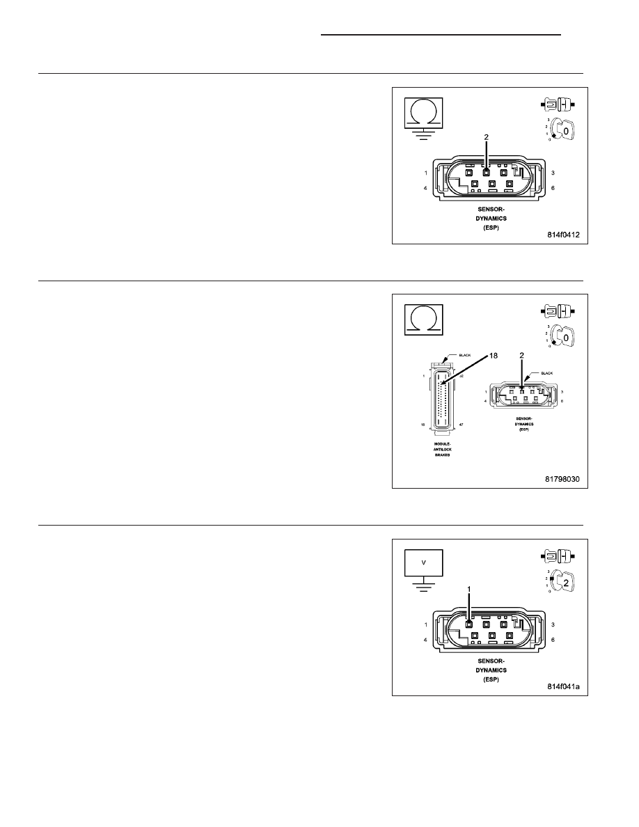
CHECK THE (D52) DYNAMICS SENSOR HIGH DATA LINK CIRCUIT FOR A SHORT TO GROUND

Turn the ignition off.

Measure the resistance of the (D52) Dynamics Sensor High Data Link
circuit between ground and the Dynamics Sensor harness connector.

Is the resistance below 5.0 ohms?

Yes

>> Repair the (D52) Dynamics Sensor High Data Link circuit

for a short to ground.

Perform ABS VERIFICATION TEST - VER 1. (Refer to 5 -
BRAKES - STANDARD PROCEDURE).

No

>> Go To 5

5.

CHECK THE (D52) DYNAMICS SENSOR HIGH DATA LINK CIRCUIT FOR AN OPEN

Measure the resistance of the (D52) Dynamics Sensor High Data Link
circuit between the Dynamics Sensor harness connector and the Anti-
Lock Brakes Module harness connector.

Is the resistance below 5.0 ohms?

Yes

>> Go To 6

No

>> Repair the (D52) Dynamics Sensor High Data Link circuit

for an open.

Perform ABS VERIFICATION TEST - VER 1. (Refer to 5 -
BRAKES - STANDARD PROCEDURE).

6.

CHECK THE (D51) DYNAMICS SENSOR LOW DATA LINK CIRCUIT FOR A SHORT TO VOLTAGE

Turn the ignition on.

Measure the voltage of the (D51) Dynamics Sensor Low Data Link cir-
cuit.

Is there any voltage present?

Yes

>> Repair the (D51) Dynamics Sensor Low Data Link circuit for

a short to voltage.

Perform ABS VERIFICATION TEST - VER 1. (Refer to 5 -
BRAKES - STANDARD PROCEDURE).

No

>> Go To 7

5 - 370

BRAKES - ABS ELECTRICAL DIAGNOSTICS

LX

7.

CHECK THE (D51) DYNAMICS SENSOR LOW DATA LINK CIRCUIT FOR A SHORT TO GROUND

Turn the ignition off.

Measure the resistance of the (D51) Dynamics Sensor Low Data Link
circuit between ground and the Dynamics Sensor harness connector.

Is the resistance below 5.0 ohms?

Yes

>> Repair the (D51) Dynamics Sensor Low Data Link circuit for

a short to ground.

Perform ABS VERIFICATION TEST - VER 1. (Refer to 5 -
BRAKES - STANDARD PROCEDURE).

No

>> Go To 8

8.

CHECK THE (D51) DYNAMICS SENSOR LOW DATA LINK CIRCUIT FOR AN OPEN

Measure the resistance of the (D51) Dynamics Sensor Low Data Link
circuit between the Dynamics Sensor harness connector and the Anti-
Lock Brakes Module harness connector.

Is the resistance below 5.0 ohms?

Yes

>> Replace the Dynamics Sensor in accordance with the Ser-

vice Information.

Perform ABS VERIFICATION TEST - VER 1. (Refer to 5 -
BRAKES - STANDARD PROCEDURE).

No

>> Repair the (D51) Dynamics Sensor Low Data Link circuit for

an open.

Perform ABS VERIFICATION TEST - VER 1. (Refer to 5 -
BRAKES - STANDARD PROCEDURE).

LX

BRAKES - ABS ELECTRICAL DIAGNOSTICS

5 - 371

U1104–CAN C BUS CRC PERFORMANCE

For a complete wiring diagram Refer to Section 8W.

5 - 372

BRAKES - ABS ELECTRICAL DIAGNOSTICS

LX

When Monitored:
With the ignition on.

Set Condition:
If the Anti-Lock Brakes Module detects an invalid CAN message from the Dynamics Sensor.

Possible Causes

WIRING HARNESS, TERMINAL, CONNECTOR DAMAGE

(D52) DYNAMICS SENSOR HIGH DATA LINK CIRCUIT SHORTED TO GROUND, VOLTAGE, OR OPEN

(D51) DYNAMICS SENSOR LOW DATA LINK CIRCUIT SHORTED TO GROUND, VOLTAGE, OR OPEN

DYNAMICS SENSOR

ANTI-LOCK BRAKES MODULE

Diagnostic Test

1.

VERIFY DTC IS ACTIVE

Turn the ignition on.

With the scan tool, read and record ABS DTCs.

With the scan tool, read and record Environmental Data (EV Data).

With the scan tool, erase ABS DTCs.

Cycle the ignition switch.

With the scan tool, read ABS DTCs.

Does this DTC reset?

Yes

>> Go To 2

No

>> Perform the ABS Intermittent Condition diagnostic procedure in this Section.

Perform ABS VERIFICATION TEST - VER 1. (Refer to 5 - BRAKES - STANDARD PROCEDURE).

2.

INSPECT RELATED WIRING HARNESS, TERMINALS, & CONNECTORS

Visually inspect the related wiring harness. Look for any pinched, chafed, pierced, and partially broken wires.

Visually inspect the related wiring harness connectors. Look for broken, bent, pushed out, and corroded terminals.

Were any problems found?

Yes

>> Repair as necessary.

Perform ABS VERIFICATION TEST - VER 1. (Refer to 5 - BRAKES - STANDARD PROCEDURE).

No

>> Go To 3

3.

CHECK THE (D52) DYNAMICS SENSOR HIGH DATA LINK CIRCUIT FOR A SHORT TO VOLTAGE

Disconnect the Anti-Lock Brakes Module harness connector.

Disconnect the Dynamics Sensor harness connector.

Turn the ignition on.

Measure the voltage of the (D52) Dynamics Sensor High Data Link cir-
cuit.

Is there any voltage present?

Yes

>> Repair the (D52) Dynamics Sensor High Data Link circuit

for a short to voltage.

Perform ABS VERIFICATION TEST - VER 1. (Refer to 5 -
BRAKES - STANDARD PROCEDURE).

No

>> Go To 4

LX

BRAKES - ABS ELECTRICAL DIAGNOSTICS

5 - 373


Content   ..  230  231  232  233   ..