Chrysler 300/300 Touring/300C, Dodge Magnum. Manual - part 2316


  Index      Chrysler     Chrysler 300/300 Touring/300C, Dodge Magnum - service repair manual


Search            


Content   ..  2314  2315  2316  2317   ..


Chrysler 300/300 Touring/300C, Dodge Magnum. Manual - part 2316


ING).

3.

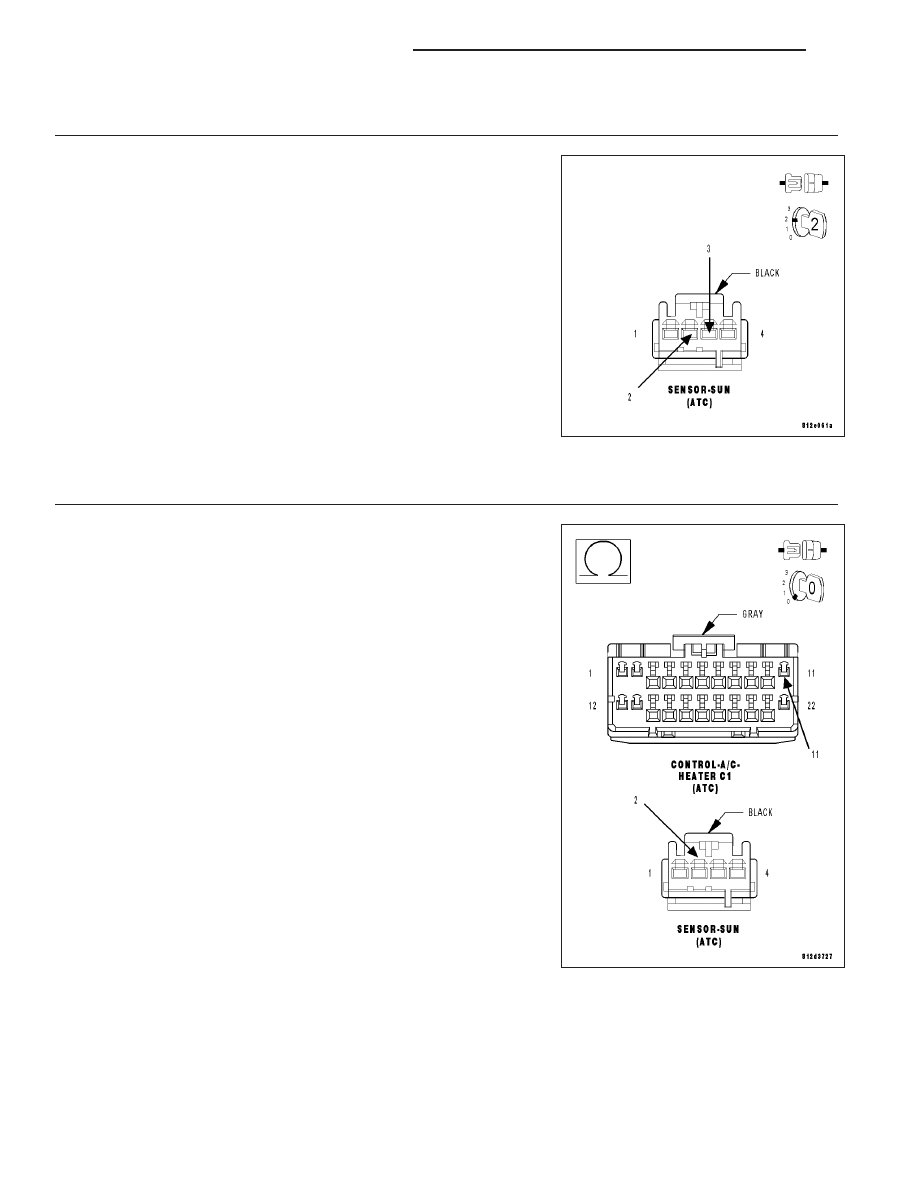
CHECK (G939) SUN SENSOR RETURN CIRCUIT FUNCTION

Turn the ignition off.

Connect a jumper wire between the (L24) Auto Headlamps Signal cir-
cuit and the (G939) Sun Sensor Return circuit in the Sun Sensor har-
ness connector.

Turn the ignition on.

With the scan tool in HVAC, select Data Display and read the Ambient
Light Sensor voltage.

Is the voltage below 0.2 volts?

Yes

>> Replace the Sun Sensor in accordance with the Service

Information.

Perform BODY VERIFICATION TEST – VER 1. (Refer to 8
-

ELECTRICAL/ELECTRONIC

CONTROL

MODULES/

FRONT CONTROL MODULE - DIAGNOSIS AND TEST-
ING).

No

>> Go To 4

4.

CHECK (G939) SUN SENSOR RETURN CIRCUIT FOR AN OPEN

Turn the ignition off.

Disconnect the A/C Heater Control C1 harness connector.

Measure the resistance of the (G939) Sun Sensor Return circuit
between the Sun Sensor harness connector and the A/C Heater Control
C1 harness connector.

Is the resistance below 5.0 ohms?

Yes

>> Replace the A/C Heater Control in accordance with the Ser-

vice Information.

Perform BODY VERIFICATION TEST – VER 1. (Refer to 8
-

ELECTRICAL/ELECTRONIC

CONTROL

MODULES/

FRONT CONTROL MODULE - DIAGNOSIS AND TEST-
ING).

No

>> Repair the (G939) Sun Sensor Return circuit for an open.

Perform BODY VERIFICATION TEST – VER 1. (Refer to 8
-

ELECTRICAL/ELECTRONIC

CONTROL

MODULES/

FRONT

CONTROL

MODULE

-

DIAGNOSIS

AND

TESTING).

24 - 298

HVAC - ELECTRICAL DIAGNOSTICS

LX

5.

CHECK (L24) AUTO HEADLAMPS SIGNAL CIRCUIT FOR AN OPEN

Turn the ignition off.

Disconnect the A/C Heater Control C1 harness connector.

Measure the resistance of the (L24) Auto Headlamps Signal circuit
between the Sun Sensor harness connector and the A/C Heater Control
C1 harness connector.

Is the resistance below 5.0 ohms?

Yes

>> Replace the A/C Heater Control in accordance with the Ser-

vice Information.

Perform BODY VERIFICATION TEST – VER 1. (Refer to 8
-

ELECTRICAL/ELECTRONIC

CONTROL

MODULES/

FRONT CONTROL MODULE - DIAGNOSIS AND TEST-
ING).

No

>> Repair the (L24) Auto Headlamps Signal circuit for an open.

Perform BODY VERIFICATION TEST – VER 1. (Refer to 8
-

ELECTRICAL/ELECTRONIC

CONTROL

MODULES/

FRONT CONTROL MODULE - DIAGNOSIS AND TEST-
ING).

LX

HVAC - ELECTRICAL DIAGNOSTICS

24 - 299

U0019–CAN B BUS (ATC)

For a complete wiring diagram Refer to Section 8W.

24 - 300

HVAC - ELECTRICAL DIAGNOSTICS

LX

When Monitored:
Continuously

Set Condition:
If the CAN B Bus (+) or CAN B Bus (-) circuit is open, shorted to voltage, or shorted to ground.

Possible Causes

ACTIVE U0019 CAN B BUS DTC IN FRONT CONTROL MODULE

(D55) CAN B BUS (+) CIRCUIT OPEN

(D54) CAN B BUS (-) CIRCUIT OPEN

A/C HEATER CONTROL

Diagnostic Test

1.

VERIFY DTC U0019–CAN B BUS IS ACTIVE

Turn the ignition on.

With the scan tool, read HVAC DTCs.

Does the scan tool display active: U0019–CAN B BUS?

Yes

>> Go To 2

No

>> If the DTC is stored, check for an intermittent condition by inspecting the related wiring harness for

chafed, pierced, pinched, and partially broken wires. Also, inspect the related connectors for broken,
bent, pushed out, spread, corroded, or contaminated terminals.

Perform BODY VERIFICATION TEST – VER 1. (Refer to 8 - ELECTRICAL/ELECTRONIC CONTROL
MODULES/FRONT CONTROL MODULE - DIAGNOSIS AND TESTING).

2.

CHECK FOR ACTIVE CAN B BUS RELATED DTCS IN THE FRONT CONTROL MODULE (FCM)

With the scan tool, read Front Control Module (FCM) DTCs

Does the scan tool display any active CAN B BUS related DTCs?

Yes

>> Diagnose and repair the DTC(s). (Refer to 8 - ELECTRICAL/ELECTRONIC CONTROL MODULES -

DIAGNOSIS AND TESTING).

No

>> Go To 3

LX

HVAC - ELECTRICAL DIAGNOSTICS

24 - 301


Content   ..  2314  2315  2316  2317   ..