Chrysler 300/300 Touring/300C, Dodge Magnum. Manual - part 2299


  Index      Chrysler     Chrysler 300/300 Touring/300C, Dodge Magnum - service repair manual


Search            


Content   ..  2297  2298  2299  2300   ..


Chrysler 300/300 Touring/300C, Dodge Magnum. Manual - part 2299


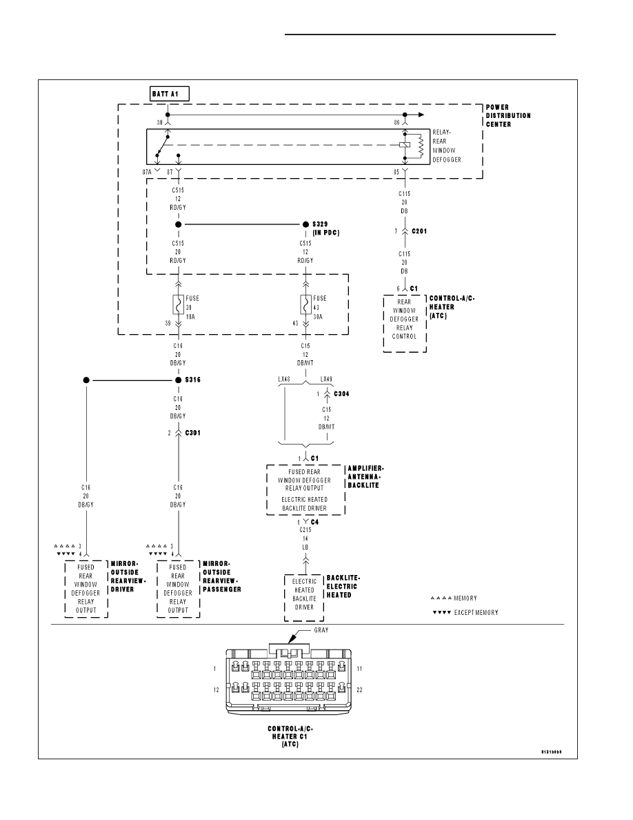
B106C–REAR DEFROST CONTROL CIRCUIT HIGH (ATC)

For a complete wiring diagram Refer to Section 8W.

24 - 230

HVAC - ELECTRICAL DIAGNOSTICS

LX

When Monitored:
With ignition on.

Set Condition:
If the EBL output is turned on and the (C115) Rear Window Defogger Relay Control circuit is either shorted to
voltage or open.

Possible Causes

(C115) REAR WINDOW DEFOGGER RELAY CONTROL CIRCUIT SHORTED TO VOLTAGE

(C115) REAR WINDOW DEFOGGER RELAY CONTROL CIRCUIT OPEN

REAR WINDOW DEFOGGER RELAY

A/C HEATER CONTROL

NOTE: This DTC must be active for the results of this test to be valid. Do not perform this test if this DTC
is stored. Refer to HVAC System Test (ATC) for stored DTC test procedures.

Diagnostic Test

1.

INSTALL A SUBSTITUTE REAR WINDOW DEFOGGER RELAY & THEN CHECK FOR DTC B106C–REAR
DEFROST CONTROL CIRCUIT HIGH

Turn the ignition on.

Verify that the EBL mode switch is off.

Turn the ignition off.

Install a substitute Rear Window Defogger Relay.

Turn the ignition on.

With the scan tool, erase HVAC DTCs.

Turn the ignition off, wait 10 seconds, and turn the ignition on.

Press the EBL mode switch is on.

With the scan tool, read HVAC DTCs.

Does the scan tool display: B106C–REAR DEFROST CONTROL
CIRCUIT HIGH?

Yes

>> Go To 2

No

>> Replace the original Rear Window Defogger Relay in accor-

dance with the Service Information.

Perform BODY VERIFICATION TEST – VER 1. (Refer to 8
-

ELECTRICAL/ELECTRONIC

CONTROL

MODULES/

FRONT CONTROL MODULE - DIAGNOSIS AND TEST-
ING).

LX

HVAC - ELECTRICAL DIAGNOSTICS

24 - 231

2.

CHECK (C115) REAR WINDOW DEFOGGER RELAY CONTROL CIRCUIT FOR A SHORT TO VOLTAGE

Turn the ignition on.

Verify that the EBL mode switch is off.

Turn the ignition off.

Remove the substitute Rear Window Defogger Relay.

Disconnect the A/C Heater Control C1 harness connector.

Turn the ignition on.

Measure the voltage of the (C115) Rear Window Defogger Relay Con-
trol circuit.

Is the voltage above 0.2 volts?

Yes

>> Repair the (C115) Rear Window Defogger Relay Control

circuit for a short to voltage. Reinstall the original Rear Win-
dow Defogger Relay.

Perform BODY VERIFICATION TEST – VER 1. (Refer to 8
-

ELECTRICAL/ELECTRONIC

CONTROL

MODULES/

FRONT CONTROL MODULE - DIAGNOSIS AND TEST-
ING).

No

>> Go To 3

3.

CHECK (C115) REAR WINDOW DEFOGGER RELAY CONTROL CIRCUIT FOR AN OPEN

Turn the ignition off.

Measure the resistance of the (C115) Rear Window Defogger Relay
Control circuit between the Rear Window Defogger Relay connector ter-
minal 85 in the PDC and the A/C Heater Control C1 harness connector.

Is the resistance below 5.0 ohms?

Yes

>> Replace the A/C Heater Control in accordance with the Ser-

vice Information. Reinstall the original Rear Window Defog-
ger Relay.

Perform BODY VERIFICATION TEST – VER 1. (Refer to 8
-

ELECTRICAL/ELECTRONIC

CONTROL

MODULES/

FRONT CONTROL MODULE - DIAGNOSIS AND TEST-
ING).

No

>> Repair the (C115) Rear Window Defogger Relay Control

circuit for an open. Reinstall the original Rear Window
Defogger Relay.

Perform BODY VERIFICATION TEST – VER 1. (Refer to 8
-

ELECTRICAL/ELECTRONIC

CONTROL

MODULES/

FRONT CONTROL MODULE - DIAGNOSIS AND TEST-
ING).

24 - 232

HVAC - ELECTRICAL DIAGNOSTICS

LX

B1001–A/C SWITCH REQUEST INPUT CIRCUIT LOW (ATC)

For a complete wiring diagram Refer to Section 8W.

Theory of Operation

The switch input changes when the switch is pushed down. A stored DTC B1001 indicates that the A/C mode switch
was stuck in a pushed position for more than 10 minutes, but has since returned to its normal state. An active DTC
B1001 indicates that the A/C mode switch is stuck in a pushed position. An active DTC B1001 will prevent proper
A/C mode switch and status indicator function.

When Monitored:
With the ignition on.

Set Condition:
If the A/C mode switch stays in a pushed position for more than 10 minutes.

Possible Causes

OBJECT HOLDING A/C MODE SWITCH IN A PUSHED POSITION

SUBSTANCE CAUSING A/C MODE SWITCH TO GET STUCK IN A PUSHED POSITION

A/C HEATER CONTROL

Diagnostic Test

1.

INSPECT THE A/C HEATER CONTROL FOR DAMAGE

Inspect the A/C Heater Control for damage.

Is the A/C Heater Control damaged?

Yes

>> Replace the A/C Heater Control in accordance with the Service Information.

Perform BODY VERIFICATION TEST – VER 1. (Refer to 8 - ELECTRICAL/ELECTRONIC CONTROL
MODULES/FRONT CONTROL MODULE - DIAGNOSIS AND TESTING).

No

>> Go To 2

2.

INSPECT FOR OBJECT OR SUBSTANCE CAUSING THE A/C MODE SWITCH TO STAY OR STICK IN A
PUSHED POSITION

Inspect the A/C Heater Control for anything that would cause the A/C mode switch to stay or stick in a pushed
position.

Is anything present that would cause the A/C mode switch to stay or stick in a pushed position?

Yes

>> Repair as necessary.

Perform BODY VERIFICATION TEST – VER 1. (Refer to 8 - ELECTRICAL/ELECTRONIC CONTROL
MODULES/FRONT CONTROL MODULE - DIAGNOSIS AND TESTING).

No

>> Go To 3

3.

CHECK FOR NORMAL A/C MODE SWITCH & STATUS INDICATOR FUNCTION

Turn the ignition on.

Set the Blower control to any position except Off.

Set the Mode control to any position except Auto.

Press the A/C mode switch on and off several times while observing the A/C status indicator.

Does the A/C status indicator turn on and off?

Yes

>> Go To 4

No

>> Replace the A/C Heater Control in accordance with the Service Information.

Perform BODY VERIFICATION TEST – VER 1. (Refer to 8 - ELECTRICAL/ELECTRONIC CONTROL
MODULES/FRONT CONTROL MODULE - DIAGNOSIS AND TESTING).

LX

HVAC - ELECTRICAL DIAGNOSTICS

24 - 233


Content   ..  2297  2298  2299  2300   ..