Chrysler 300/300 Touring/300C, Dodge Magnum. Manual - part 2294


  Index      Chrysler     Chrysler 300/300 Touring/300C, Dodge Magnum - service repair manual


Search            


Content   ..  2292  2293  2294  2295   ..


Chrysler 300/300 Touring/300C, Dodge Magnum. Manual - part 2294


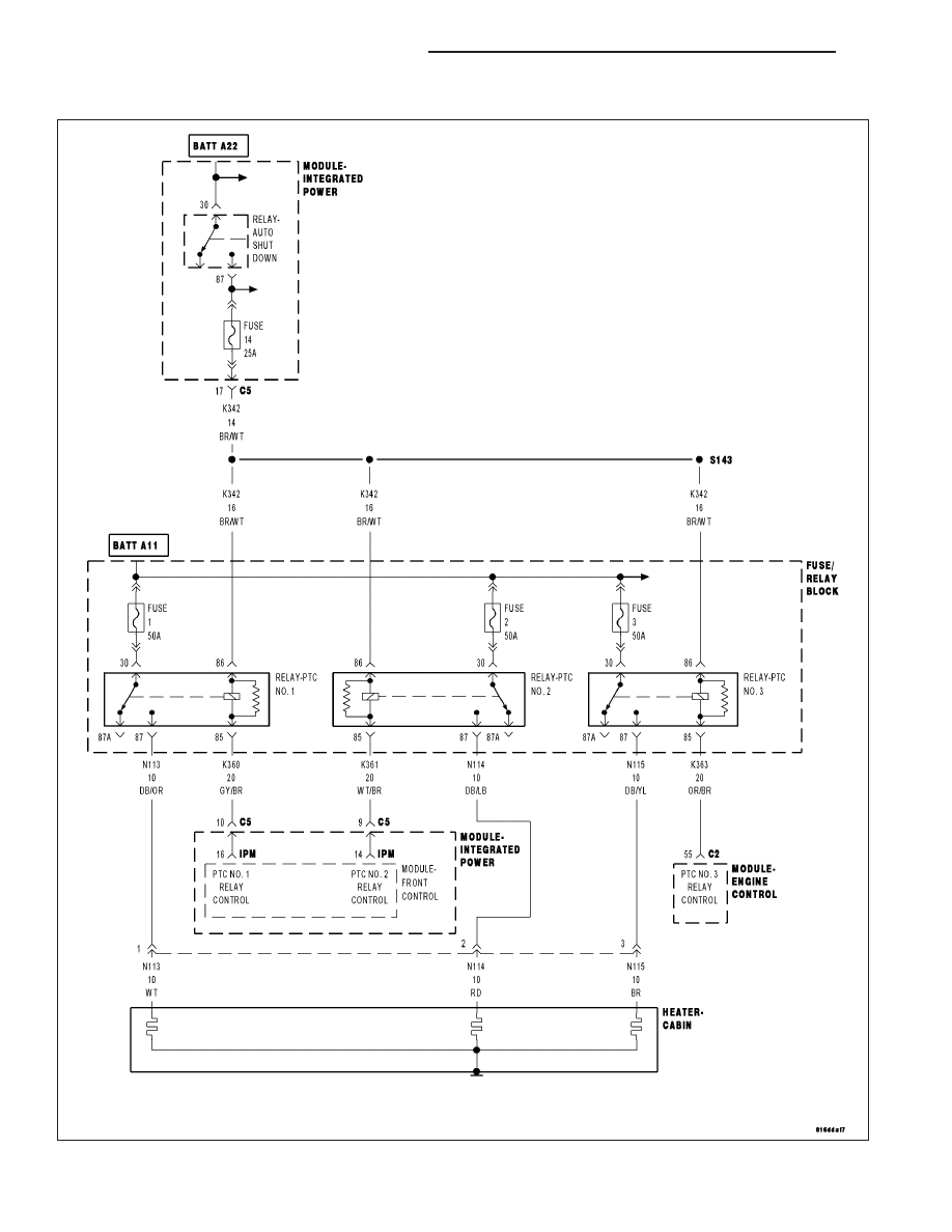
B10B9–CABIN HEATER 2 CONTROL CIRCUIT HIGH (FCM)

For a complete wiring diagram Refer to Section 8W

24 - 210

HVAC - ELECTRICAL DIAGNOSTICS

LX

When Monitored:
With the ignition on, the ASD Relay energized, and the PTC No. 2 Relay command on.

Set Condition:
If the Front Control Module (FCM) detects that the (K361) PTC No. 2 Relay Control circuit voltage is shorted
to voltage.

Possible Causes

(K361) PTC NO. 2 RELAY CONTROL CIRCUIT SHORTED TO VOLTAGE

(K361) PTC NO. 2 RELAY CONTROL CIRCUIT OPEN OR HIGH RESISTANCE

PTC NO. 2 RELAY

FRONT CONTROL MODULE (FCM)

Diagnostic Test

1.

VERIFY THAT THE DTC IS ACTIVE

WARNING: WHEN THE ENGINE IS OPERATING, DO NOT STAND IN A DIRECT LINE WITH THE FAN. DO NOT
PUT YOUR HANDS NEAR THE PULLEYS, BELTS OR FAN. DO NOT WEAR LOOSE CLOTHING.

NOTE: If the FCM detects and stores a DTC, the FCM also stores the environmental conditions under which
the DTC was set.

NOTE: Before erasing stored DTCs, record these conditions. Attempting to duplicate these conditions may
assist when checking for an active DTC.
Turn the ignition on.

With the scan tool, erase FCM DTCs.

With the scan tool, actuate the PTC No. 2 Relay.

Monitor the scan tool for at least two minutes.

With the scan tool, read FCM DTCs.

Is the status Active for this DTC?

Yes

>> Go To 2

No

>> Check for an intermittent condition by inspecting the related wiring harness for chaffed, pierced,

pinched, and partially broken wires. Also, inspect the related connectors for broken, bent, pushed out,
spread, corroded, or contaminated terminals.

2.

CHECK PTC NO. 2 RELAY

With the scan tool, erase FCM DTCs.

Turn the ignition off.

Remove the PTC No. 2 Relay.

Turn the ignition on.

With the scan tool, actuate the PTC No. 2 Relay.

With the scan tool, read FCM DTCs.

NOTE: The scan tool should display an open circuit DTC with the
PTC No. 2 Relay removed.

Does the scan tool display: B10B9–CABIN HEATER 2 CON-
TROL CIRCUIT HIGH?

Yes

>> Go To 3

No

>> Replace the PTC No. 2 Relay in accordance with the Ser-

vice Information.

Perform the BODY VERIFICATION TEST VER 1. (Refer to
8 - ELECTRICAL/ELECTRONIC CONTROL MODULES/
FRONT

CONTROL

MODULE

-

DIAGNOSIS

AND

TESTING).

LX

HVAC - ELECTRICAL DIAGNOSTICS

24 - 211

3.

CHECK (K361) PTC NO. 2 RELAY CONTROL CIRCUIT FOR A SHORT TO VOLTAGE

Turn the ignition off.

Disconnect the FCM from the Power Module.

Remove the ASD Relay from the IPM.

Connect a jumper wire between cavity 30 and cavity 87 of the ASD
Relay Connector.

Turn the ignition on.

Measure the voltage of the (K361) PTC No. 2 Relay Control circuit in
the PTC No. 2 Relay connector.

Is there any voltage present?

Yes

>> Repair the (K361) PTC No. 2 Relay Control circuit for a

short to voltage.

Perform the BODY VERIFICATION TEST VER 1. (Refer to
8 - ELECTRICAL/ELECTRONIC CONTROL MODULES/
FRONT CONTROL MODULE - DIAGNOSIS AND TEST-
ING).

No

>> Go To 4

4.

CHECK (K361) PTC NO. 2 RELAY CONTROL FOR AN OPEN OR HIGH RESISTANCE

Turn the ignition off.

Measure the resistance of the (K361) PTC No. 2 Relay Control circuit
between the PTC No. 2 Relay connector and the FCM connector.

Is the resistance below 10.0 ohms?

Yes

>> Go To 5

No

>> Repair the (K361) PTC No. 2 Relay Control circuit for an

open or high resistance.

Perform the BODY VERIFICATION TEST VER 1. (Refer to
8 - ELECTRICAL/ELECTRONIC CONTROL MODULES/
FRONT

CONTROL

MODULE

-

DIAGNOSIS

AND

TESTING).

24 - 212

HVAC - ELECTRICAL DIAGNOSTICS

LX

5.

INSPECT RELATED WIRING & CHECK FOR TSBs

Using the wiring diagram/schematic as a guide, inspect the wiring and connectors between the PTC No. 2 Relay
and the FCM.

Look for any chafed, pierced, pinched, or partially broken wires.

Look for broken, bent, pushed out or corroded terminals.

Refer to any Technical Service Bulletins that may apply.

Were any problems found?

Yes

>> Repair as necessary.

Perform the BODY VERIFICATION TEST VER 1. (Refer to 8 - ELECTRICAL/ELECTRONIC CONTROL
MODULES/FRONT CONTROL MODULE - DIAGNOSIS AND TESTING).

No

>> Replace the FCM in accordance with the Service Information.

Perform the BODY VERIFICATION TEST VER 1. (Refer to 8 - ELECTRICAL/ELECTRONIC CONTROL
MODULES/FRONT CONTROL MODULE - DIAGNOSIS AND TESTING).

LX

HVAC - ELECTRICAL DIAGNOSTICS

24 - 213


Content   ..  2292  2293  2294  2295   ..