Content .. 2265 2266 2267 2268 ..
Chrysler 300/300 Touring/300C, Dodge Magnum. Manual - part 2267
Theory of Operation
NOTE: This DTC will display as active if the ignition is not cycled after running the Actuator Circuit Test /
Door Calibration Function. Otherwise, it will display as stored until cleared.
By running the Actuator Circuit Test / Door Calibration Function, the A/C Heater Control can identify up to
three door driver circuits shorted simultaneously. A DTC 72 will set if more than three door driver circuits
are shorted in the same direction (e.g. four door driver circuits all shorted to ground) or if two or more door
driver circuits are shorted with at least one door driver circuit shorted to ignition and one door driver circuit
shorted to ground. To ensure a proper diagnosis, diagnose and repair Actuator Circuit Test faults in the
following order: If present, diagnose and repair DTC 72 first, then DTC 62, then DTC 61, then DTCs 64, 68,
or 71, and finally DTCs 63, 67, or 69. In addition, always test the door driver circuits after each repair by
clearing DTCs, and then running the Actuator Circuit Test / Door Calibration Function, and then checking for
DTCs.
•
When Monitored:
When running the Actuator Circuit Test / Door Calibration Function.
•
Set Condition:
If the A/C Heater Control detects a short to voltage on the (C66) Mode Door Common Driver circuit / (C55)
Left Blend Door Common Driver circuit / (C68) Recirculation Door Common Driver circuit.
Possible Causes
(C66) MODE DOOR COMMON DRIVER CIRCUIT / (C55) LEFT BLEND DOOR COMMON DRIVER CIRCUIT /
(C68) RECIRCULATION DOOR COMMON DRIVER CIRCUIT SHORTED TO VOLTAGE
A/C HEATER CONTROL
Diagnostic Test
1.
CHECK THE (C66) MODE DOOR COMMON DRIVER CIRCUIT, THE (C55) LEFT BLEND DOOR COMMON
DRIVER CIRCUIT, & THE (C68) RECIRCULATION DOOR COMMON DRIVER CIRCUIT FOR A SHORT TO
VOLTAGE
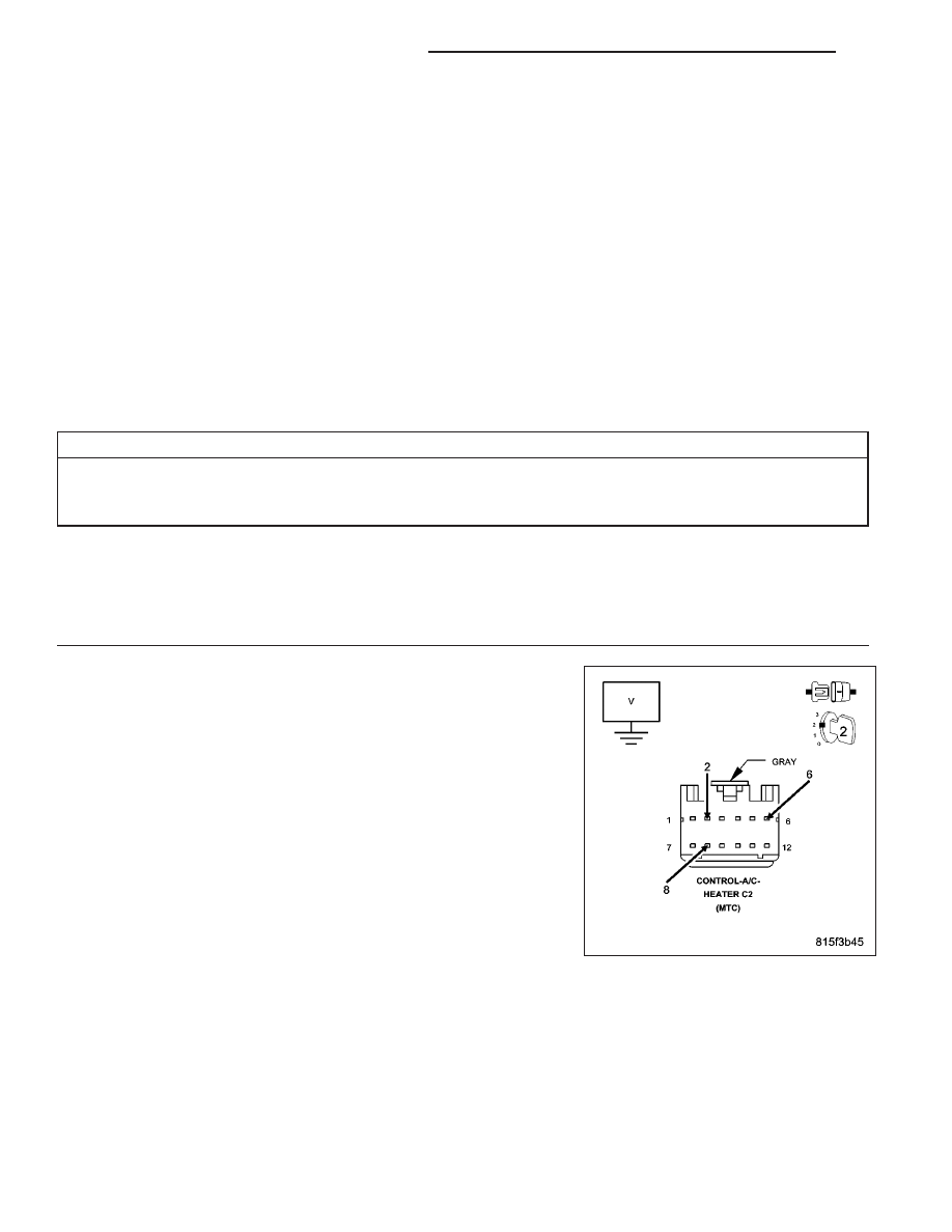
Turn the ignition off.
Disconnect the A/C Heater Control C2 harness connector.
Turn the ignition on.
Measure the voltage of the (C66) Mode Door Common Driver circuit,
(C55) Left Blend Door Common Driver circuit, and the (C68) Recircula-
tion Door Common Driver circuit.
Is the voltage above 0.2 volts on any of the circuits?
Yes
>> Repair all circuits with a voltage above 0.2 volts for a short
to voltage.
Perform BODY VERIFICATION TEST – VER 1. (Refer to 8
-
ELECTRICAL/ELECTRONIC
CONTROL
MODULES/
FRONT CONTROL MODULE - DIAGNOSIS AND TEST-
ING).
No
>> Go To 2
24 - 102
HVAC - ELECTRICAL DIAGNOSTICS
LX