Content .. 2264 2265 2266 2267 ..
Chrysler 300/300 Touring/300C, Dodge Magnum. Manual - part 2266
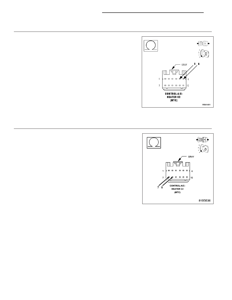
8.
CHECK THE (C55) LEFT BLEND DOOR COMMON DRIVER CIRCUIT FOR A SHORT TO THE (C255) LEFT
BLEND DOOR DRIVER CIRCUIT
Disconnect the Left Blend Door Actuator harness connector.
Measure the resistance between the (C55) Left Blend Door Common
Driver Circuit and the (C255) Left Blend Door Driver circuit in the A/C
Heater Control C2 harness connector.
Is the resistance below 10k ohms?
Yes
>> Repair the (C55) Left Blend Door Common Driver Circuit
for a short to the (C255) Left Blend Door Driver circuit.
Perform BODY VERIFICATION TEST – VER 1. (Refer to 8
-
ELECTRICAL/ELECTRONIC
CONTROL
MODULES/
FRONT CONTROL MODULE - DIAGNOSIS AND TEST-
ING).
No
>> Replace the Left Blend Door Actuator in accordance with
the Service Information.
Perform BODY VERIFICATION TEST – VER 1. (Refer to 8
-
ELECTRICAL/ELECTRONIC
CONTROL
MODULES/
FRONT CONTROL MODULE - DIAGNOSIS AND TEST-
ING).
9.
CHECK THE RECIRCULATION DOOR ACTUATOR CIRCUIT RESISTANCE
Measure the resistance between the (C68) Recirculation Door Common
Driver Circuit and the (C268) Recirculation Door Driver circuit in the A/C
Heater Control C2 harness connector.
Is the resistance below 30.0 ohms?
Yes
>> Go To 10
No
>> Go To 11
24 - 98
HVAC - ELECTRICAL DIAGNOSTICS
LX