Content .. 2183 2184 2185 2186 ..
Chrysler 300/300 Touring/300C, Dodge Magnum. Manual - part 2185
SUNROOF - SERVICE INFORMATION
DESCRIPTION
The power sunroof system allows the sunroof to be opened, closed or placed in the vent position electrically by
actuating a switch in the overhead console. The sunroof system receives battery feed through a fuse in the Power
Distribution Center (PDC). The sunroof will operate normally with the key in any position while the Accessory Delay
system is active.
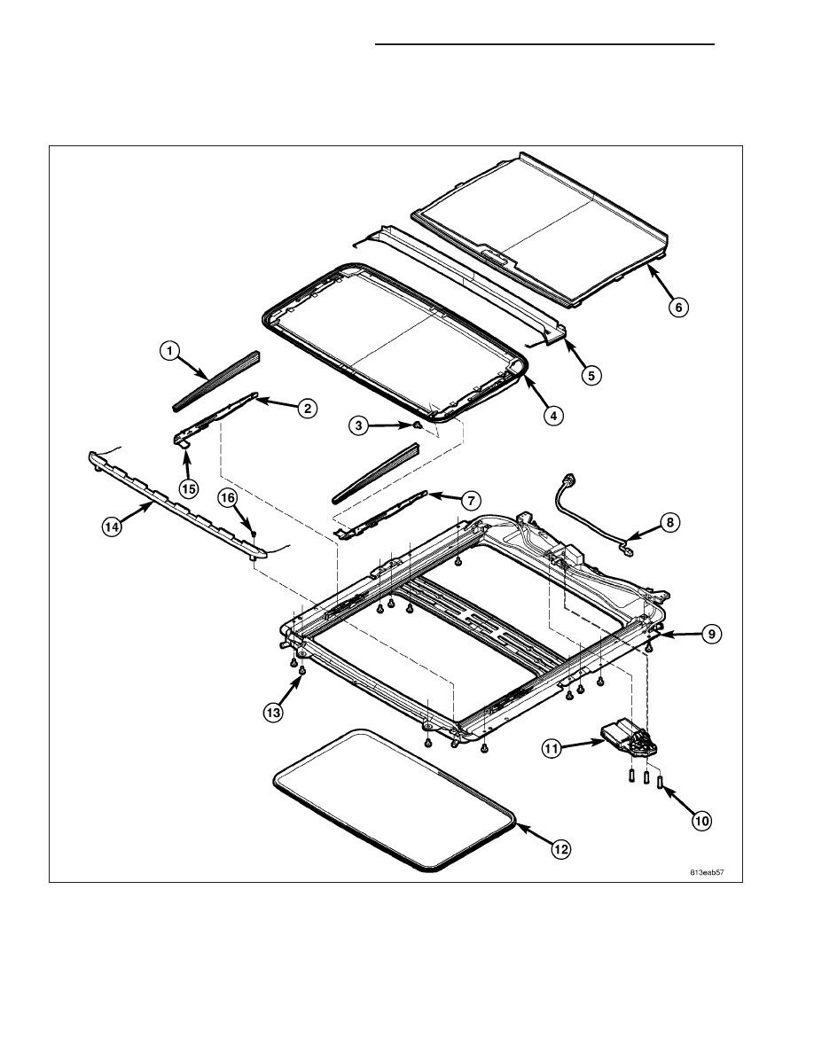
EXPLODED VIEW
23 - 288
SUNROOF - SERVICE INFORMATION
LX