Content .. 2150 2151 2152 2153 ..
Chrysler 300/300 Touring/300C, Dodge Magnum. Manual - part 2152
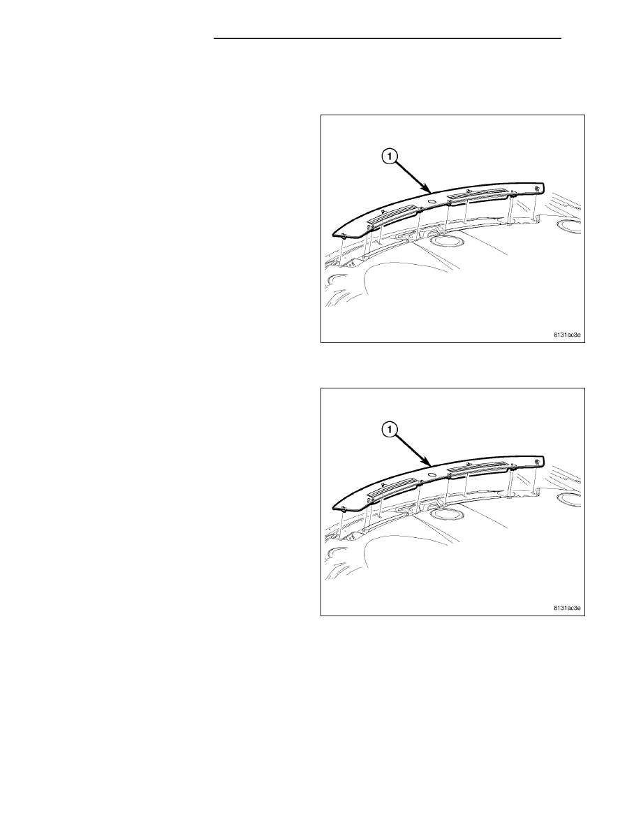
GRILLE-DEFROSTER
REMOVAL
1. Before proceeding with the following repair proce-
dure, review all warnings and cautions (Refer to 23
- BODY/INSTRUMENT PANEL - WARNING).
2. Using a trim stick C-4755 or equivalent, gently pry
between the instrument panel top cover and the
defroster grille (1) to release the snap clip retainers
that secure the defroster grille.
3. Remove the defroster grille.
INSTALLATION
1. Before proceeding with the following repair proce-
dure, review all warnings and cautions (Refer to 23
- BODY/INSTRUMENT PANEL - WARNING).
2. Position the defroster grille (1) onto the top of the
instrument panel.
3. Carefully push down on the defroster grille to fully
seat the snap clip retainers into the instrument
panel top cover.
23 - 156
INSTRUMENT PANEL
LX