Chrysler 300/300 Touring/300C, Dodge Magnum. Manual - part 2016


  Index      Chrysler     Chrysler 300/300 Touring/300C, Dodge Magnum - service repair manual


Search            


Content   ..  2014  2015  2016  2017   ..


Chrysler 300/300 Touring/300C, Dodge Magnum. Manual - part 2016


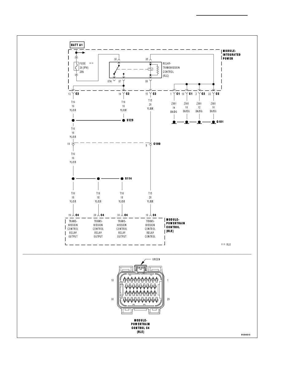
P0891-TRANSMISSION RELAY ALWAYS ON

For a complete wiring diagram Refer to Section 8W.

21 - 598

AUTOMATIC TRANSMISSION 42RLE - ELECTRICAL DIAGNOSTICS

LX

When Monitored:
After a reset (ignition key turned to the RUN position) and after a power down.

Set Condition:
Relay output (Switched Battery) is higher than 3 volts when relay is not energized by controller. Fault Set Time:
Less than 100 msec

Possible Causes

TRANSMISSION CONTROL RELAY STUCK CLOSED

(T15) TRANSMISSION CONTROL RELAY CONTROL CIRCUIT SHORT TO VOLTAGE

(T16) TRANSMISSION CONTROL RELAY OUTPUT CIRCUITS SHORT TO VOLTAGE

POWERTRAIN CONTROL MODULE

Always perform the 42RLE Pre-Diagnostic Troubleshooting Procedure before proceeding. (Refer to 21 -
TRANSMISSION/TRANSAXLE/AUTOMATIC - 42RLE - STANDARD PROCEDURE)

Theory of Operation

The transmission relay is used to supply power to the solenoid pack when in normal operating mode, and to turn off
power to produce transmission

9

limp-in

9

mode. The relay output (which supplies power to the solenoid pack) is fed

back to the controller This is referred to as SWITCHED BATTERY. After a controller reset (ignition key turned to the
RUN position or after cranking engine), the controller verifies that the relay contacts are open by checking for no
voltage on Switched battery line (ie. relay output) before the relay is energized. Transmission locked in Limp-In. MIL
on after 10 sec. of vehicle operation.

Diagnostic Test

1.

CHECK TO SEE IF DTC P0883 IS CURRENT

With the scan tool, Check the STARTS SINCE SET counter for P0883.

NOTE: This counter only applies to the last DTC set.

Is the STARTS SINCE SET counter equal to 0?

Yes

>> Go To 2

No

>> Go To 5

2.

TRANSMISSION CONTROL RELAY CONTACTS STUCK CLOSED

Turn the ignition off to the lock position.

Remove the Transmission Control Relay.

NOTE: Check connectors - Clean/repair as necessary.
Measure the resistance between the Fused B+ circuit and the Transmission Control Relay Output Circuit of the
Transmission Control Relay.

Is the resistance above 5.0 ohms?

Yes

>> Go To 3

No

>> Replace the Transmission Control Relay.

Perform 42RLE TRANSMISSION VERIFICATION TEST - VER 1. (Refer to 21 - TRANSMISSION/
TRANSAXLE/AUTOMATIC - 42RLE - STANDARD PROCEDURE)

LX

AUTOMATIC TRANSMISSION 42RLE - ELECTRICAL DIAGNOSTICS

21 - 599

3.

(T16) TRANSMISSION RELAY OUTPUT CIRCUIT SHORT TO VOLTAGE

Turn the ignition off to the lock position.

Remove the Transmission Control Relay.

NOTE: Check connectors - Clean/repair as necessary.
Ignition on, engine not running.

Measure the voltage at the (T16) Transmission Control Relay Output
circuit in the Transmission Control Relay connector.

Is the voltage above 0.5 volts?

Yes

>> Repair the (T16) Transmission Control Relay Output circuit

for a short to voltage.

Perform 42RLE TRANSMISSION VERIFICATION TEST -
VER 1. (Refer to 21 - TRANSMISSION/TRANSAXLE/AU-
TOMATIC - 42RLE - STANDARD PROCEDURE)

No

>> Go To 4

4.

(T15) TRANSMISSION CONTROL RELAY CONTROL CIRCUIT SHORT TO VOLTAGE

Turn the ignition off to the lock position.

Remove the Transmission Control Relay.

NOTE: Check connectors - Clean/repair as necessary.
Ignition on, engine not running.

NOTE: The Transmission Controller will power up the Transmis-
sion Control Relay Control circuit for approximately 3.0 seconds
after initial ignition on. Wait at least 3.0 seconds before performing
the following voltage check.

NOTE: A One-trip fault may set for P0888 Relay Always Off, disre-
gard the DTC.
Measure the voltage at the (T15) Transmission Control Relay Control
circuit after a 3.0 second wait period.

Is the voltage above 0.5 volts?

Yes

>> Repair the (T15) Transmission Control Relay Control circuit

for a short to voltage.

Perform 42RLE TRANSMISSION VERIFICATION TEST - VER 1. (Refer to 21 - TRANSMISSION/
TRANSAXLE/AUTOMATIC - 42RLE - STANDARD PROCEDURE)

No

>> Using the schematics as a guide, check the Powertrain Control Module (PCM) terminals for corrosion,

damage, or terminal push out. Pay particular attention to all power and ground circuits. If no problems
are found, replace the PCM per the Service Information. With the scan tool PERFORM QUICK LEARN,
then program Pinion Factor in the Front Control Module. (Refer to 8 - ELECTRICAL/ELECTRONIC
CONTROL MODULES/POWERTRAIN CONTROL MODULE - REMOVAL)

Perform 42RLE TRANSMISSION VERIFICATION TEST - VER 1. (Refer to 21 - TRANSMISSION/
TRANSAXLE/AUTOMATIC - 42RLE - STANDARD PROCEDURE)

21 - 600

AUTOMATIC TRANSMISSION 42RLE - ELECTRICAL DIAGNOSTICS

LX

5.

INTERMITTENT WIRING AND CONNECTORS

The conditions necessary to set the DTC are not present at this time.

Using the schematics as a guide, inspect the wiring and connectors specific to this circuit.

Wiggle the wiring and connectors while checking for shorted and open circuits.

With the scan tool, check the EATX DTC EVENT DATA to help identify the conditions in which the DTC was set.

Were there any problems found?

Yes

>> Repair as necessary.

Perform 42RLE TRANSMISSION VERIFICATION TEST - VER 1. (Refer to 21 - TRANSMISSION/
TRANSAXLE/AUTOMATIC - 42RLE - STANDARD PROCEDURE)

No

>> Test Complete.

LX

AUTOMATIC TRANSMISSION 42RLE - ELECTRICAL DIAGNOSTICS

21 - 601


Content   ..  2014  2015  2016  2017   ..