Content .. 2005 2006 2007 2008 ..
Chrysler 300/300 Touring/300C, Dodge Magnum. Manual - part 2007
8.
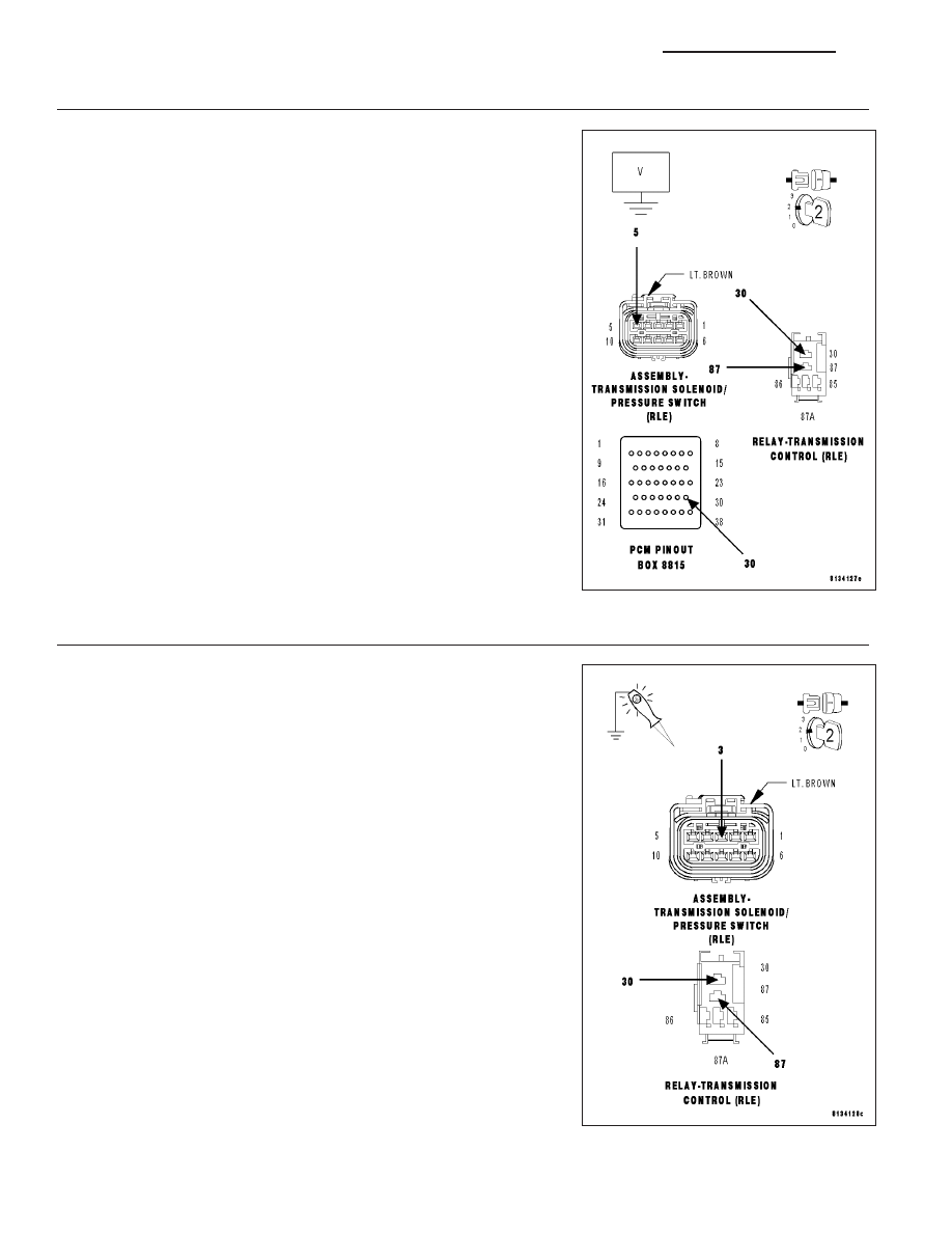
(T47) 2/4 PRESSURE SWITCH SENSE CIRCUIT SHORT TO VOLTAGE
Turn the ignition off to the lock position.
Disconnect the PCM C4 harness connector.
Disconnect the Transmission Solenoid/Pressure Switch Assembly har-
ness connector.
Remove the Transmission Control Relay.
NOTE: Check connectors - Clean/repair as necessary.
Connect a jumper wire between the (A104) Fused B+ circuit and the
(T16) Transmission Control Relay Output circuit.
Ignition on, engine not running.
Measure the voltage of the (T47) 2/4 Pressure Switch Sense circuit.
Is the voltage above 0.5 volts?
Yes
>> Repair the (T47) 2/4 Pressure Switch Sense circuit for a
short to voltage.
Perform 42RLE TRANSMISSION VERIFICATION TEST -
VER 1. (Refer to 21 - TRANSMISSION/TRANSAXLE/AU-
TOMATIC - 42RLE - STANDARD PROCEDURE)
No
>> Go To 9
9.
TRANSMISSION CONTROL RELAY OUTPUT CIRCUIT OPEN
Turn the ignition off to the lock position.
Disconnect the Transmission Solenoid/Pressure Switch Assembly har-
ness connector.
Remove the Transmission Control Relay.
NOTE: Check connectors - Clean/repair as necessary.
Connect a jumper wire between the (Internal) Fused B+ circuit and the
(T16) Transmission Control Relay Output circuit in the Transmission
Control Relay connector.
Ignition on, engine not running.
Using a 12-volt test light connected to ground, check (T16) Transmis-
sion Control Relay Output circuit in the Transmission Solenoid/Pressure
Switch Assembly harness connector.
NOTE: The test light must illuminate brightly. Compare the bright-
ness to that of a direct connection to the battery.
Does the test light illuminate brightly?
Yes
>> Using the schematics as a guide, check the Powertrain
Control Module (PCM) terminals for corrosion, damage, or
terminal push out. Pay particular attention to all power and
ground circuits. If no problems are found, replace the PCM
per the Service Information. With the scan tool PERFORM
QUICK LEARN, then program Pinion Factor in the Front
Control Module. (Refer to 8 - ELECTRICAL/ELECTRONIC
21 - 562
AUTOMATIC TRANSMISSION 42RLE - ELECTRICAL DIAGNOSTICS
LX