Chrysler 300/300 Touring/300C, Dodge Magnum. Manual - part 1985


  Index      Chrysler     Chrysler 300/300 Touring/300C, Dodge Magnum - service repair manual


Search            


Content   ..  1983  1984  1985  1986   ..


Chrysler 300/300 Touring/300C, Dodge Magnum. Manual - part 1985


3.

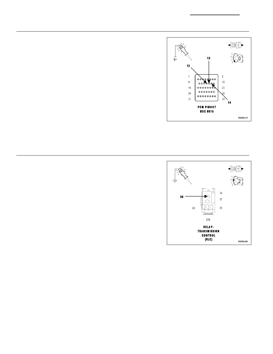
CHECKING (Z904) GROUND CIRCUIT

Turn the ignition off to the lock position.

Disconnect the PCM C4 harness connector.

NOTE: Check connectors - Clean/repair as necessary.

CAUTION: Do not probe the PCM harness connectors. Probing the
PCM harness connectors will damage the PCM terminals resulting
in poor terminal to pin connection. Install Miller Tool #8815 to per-
form diagnosis.
Using a 12-volt test light connected to 12-volts, check the (Z904)
Ground circuits in the appropriate terminals of Miller tool #8815.

NOTE: The test light must illuminate brightly. Compare the bright-
ness to that of a direct connection to the battery.

Does the test light illuminate brightly for all the Ground cir-
cuits?

Yes

>> Go To 4

No

>> Repair the Ground circuit and/or circuits for an open or high

resistance.

Perform 42RLE TRANSMISSION VERIFICATION TEST - VER 1. (Refer to 21 - TRANSMISSION/
TRANSAXLE/AUTOMATIC - 42RLE - STANDARD PROCEDURE)

4.

CHECKING (INTERNAL) FUSED B(+) CIRCUIT

Turn the ignition off to the lock position.

Remove the Transmission Control Relay.

Ignition on, engine not running.

Using a 12-volt test light connected to ground, check the (internal)
Fused B(+) circuit in the Transmission Control Relay connector.

NOTE: The Test light must illuminate brightly. Compare the bright-
ness to that of a direct connection to the battery.

Does the test light illuminate brightly?

Yes

>> Go To 5

No

>> Repair the Fused B(+) circuit for an open or high resis-

tance.

Perform 42RLE TRANSMISSION VERIFICATION TEST -
VER 1. (Refer to 21 - TRANSMISSION/TRANSAXLE/AU-
TOMATIC - 42RLE - STANDARD PROCEDURE)

21 - 474

AUTOMATIC TRANSMISSION 42RLE - ELECTRICAL DIAGNOSTICS

LX

5.

CHECKING THE (T16) TRANSMISSION CONTROL RELAY OUTPUT CIRCUIT

Turn the ignition off to the lock position.

Disconnect the PCM C4 harness connector.

Remove the Transmission Control Relay.

NOTE: Check connectors - Clean/repair as necessary.
Connect a jumper wire between (INTERNAL) Fused B(+) circuit and the
(T16) Transmission Control Relay Output circuit.

Ignition on, engine not running.

Using a 12-volt test light connected to ground, check all (T16) Trans-
mission Control Relay Output circuits in the appropriate terminals of
Miller tool #8815.

NOTE: The test light must illuminate brightly. Compare the bright-
ness to that of a direct connection to the battery.

Does the test light illuminate brightly?

Yes

>> Go To 6

No

>> Repair the (T16) Transmission Control Relay Output cir-

cuit(s) for an open or high resistance.

Perform 42RLE TRANSMISSION VERIFICATION TEST -
VER 1. (Refer to 21 - TRANSMISSION/TRANSAXLE/AU-
TOMATIC - 42RLE - STANDARD PROCEDURE)

6.

TRANSMISSION CONTROL RELAY

Turn the ignition off to the lock position.

Install a substitute Relay in place of the Transmission Control Relay.

Start the engine.

Using a voltmeter, measure the battery voltage.

With the scan tool, monitor the Transmission Switched Battery Voltage.

Compare the scan tool Transmission Switched Battery voltage to the actual battery voltage.

Is the scan tool voltage within 2.0 volts of the battery voltage?

Yes

>> Replace the Transmission Control Relay.

Perform 42RLE TRANSMISSION VERIFICATION TEST - VER 1. (Refer to 21 - TRANSMISSION/
TRANSAXLE/AUTOMATIC - 42RLE - STANDARD PROCEDURE)

No

>> Using the schematics as a guide, check the Powertrain Control Module (PCM) terminals for corrosion,

damage, or terminal push out. Pay particular attention to all power and ground circuits. If no problems
are found, replace the PCM per the Service Information. With the scan tool PERFORM QUICK LEARN,
then program Pinion Factor in the Front Control Module. (Refer to 8 - ELECTRICAL/ELECTRONIC
CONTROL MODULES/POWERTRAIN CONTROL MODULE - REMOVAL)

Perform 42RLE TRANSMISSION VERIFICATION TEST - VER 1. (Refer to 21 - TRANSMISSION/
TRANSAXLE/AUTOMATIC - 42RLE - STANDARD PROCEDURE)

LX

AUTOMATIC TRANSMISSION 42RLE - ELECTRICAL DIAGNOSTICS

21 - 475

7.

INTERMITTENT WIRING AND CONNECTORS

The conditions necessary to set the DTC are not present at this time.

Using the schematics as a guide, inspect the wiring and connectors specific to this circuit.

Wiggle the wiring and connectors while checking for shorts and open circuits.

With the scan tool, check the DTC EVENT DATA to help identify the conditions in which the DTC was set.

Were there any problems found?

Yes

>> Repair as necessary.

Perform 42RLE TRANSMISSION VERIFICATION TEST - VER 1. (Refer to 21 - TRANSMISSION/
TRANSAXLE/AUTOMATIC - 42RLE - STANDARD PROCEDURE)

No

>> Test Complete.

21 - 476

AUTOMATIC TRANSMISSION 42RLE - ELECTRICAL DIAGNOSTICS

LX

P0602-CONTROL MODULE PROGRAMMING ERROR/NOT PROGRAMMED

For a complete wiring diagram Refer to Section 8W.

When Monitored:
Check for generic software is made at power-up.

Set Condition:
If generic software is found , the MIL will light immediately. This DTC is designed to signal the technician that
the controller still has generic software installed.

Possible Causes

PCM - PROGRAMMING ERROR

Always perform the 42RLE Pre-Diagnostic Troubleshooting Procedure before proceeding. (Refer to 21 -
TRANSMISSION/TRANSAXLE/AUTOMATIC - 42RLE - STANDARD PROCEDURE)

Theory of Operation

The controller is programmed during manufacturing with generic software to facilitate testing. This software does not
have the proper calibrations to control a transmission in a vehicle. The check for generic software is made at power-
up. If generic software is found , the MIL will light immediately and the MIL will stay on even if the fault is cleared,
until the proper software is installed. Note: Transmission will be placed in limp-in mode.

Diagnostic Test

1.

CONTROL MODULE PROGRAMMING ERROR

NOTE: Controller is programmed with generic software and will not allow the correct vehicle Powertrain
management.
Record the controller part number.

Update the controller with the correct software in accordance with the Service Information.

Verify that the controller updated successfully.

Test Complete

Perform 42RLE TRANSMISSION VERIFICATION TEST - VER 1. (Refer to 21 - TRANSMISSION/
TRANSAXLE/AUTOMATIC - 42RLE - STANDARD PROCEDURE)

LX

AUTOMATIC TRANSMISSION 42RLE - ELECTRICAL DIAGNOSTICS

21 - 477


Content   ..  1983  1984  1985  1986   ..