Content .. 1979 1980 1981 1982 ..
Chrysler 300/300 Touring/300C, Dodge Magnum. Manual - part 1981
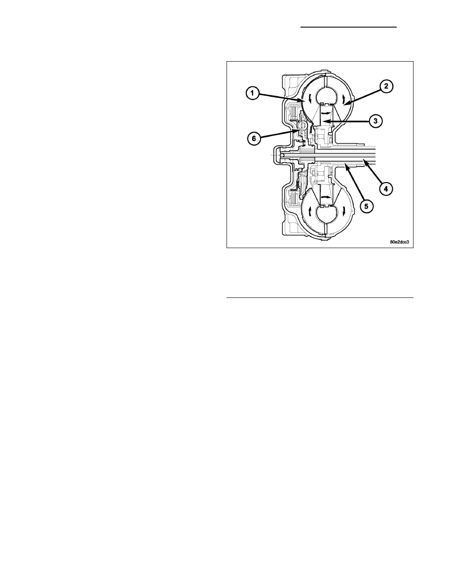
OPERATION
The converter impeller (driving member) (2), which is
integral to the converter housing and bolted to the
engine drive plate, rotates at engine speed. The con-
verter turbine (driven member) (1), which reacts from
fluid pressure generated by the impeller, rotates and
turns the transmission input shaft (4).
TURBINE
As the fluid that was put into motion by the impeller blades strikes the blades of the turbine, some of the energy and
rotational force is transferred into the turbine and the input shaft. This causes both of them (turbine and input shaft)
to rotate in a clockwise direction following the impeller. As the fluid is leaving the trailing edges of the turbine’s
blades it continues in a “hindering” direction back toward the impeller. If the fluid is not redirected before it strikes
the impeller, it will strike the impeller in such a direction that it would tend to slow it down.
1 - TURBINE
2 - IMPELLER
3 - STATOR
4 - INPUT SHAFT
5 - STATOR SHAFT
6 - TURBINE DAMPER
21 - 458
AUTOMATIC TRANSMISSION NAG1 - SERVICE INFORMATION
LX